Infiniti EX35. Manual — part 1538

WW-4
< BASIC INSPECTION >
DIAGNOSIS AND REPAIR WORKFLOW
>> GO TO 2.
2.
SYMPTOM CHECK
Check the symptom from the customer's information.
>> GO TO 3.
3.
BASIC INSPECTION
Check the operation of each part. Check that any symptom occurs other than the interviewed symptom.
>> GO TO 4.
4.
SELF-DIAGNOSIS WITH CONSULT-III
Perform the self-diagnosis with CONSULT-III. Check that any DTC is detected.
Is any DTC detected?
YES
>> GO TO 5.
NO
>> GO TO 6.
5.
TROUBLE DIAGNOSIS BY DTC
Perform the trouble diagnosis for the detected DTC. Specify the malfunctioning part.
>> GO TO 9.
6.
FAIL-SAFE ACTIVATION CHECK
Check that the symptom is applied to the fail-safe activation.
Does the fail-safe activate?
YES
>> GO TO 7.
NO
>> GO TO 8.
7.
SYSTEM DIAGNOSIS
Perform the system diagnosis for the system that the fail-safe activates. Specify the malfunctioning part.
>> GO TO 9.
8.
SYMPTOM DIAGNOSIS
Perform the symptom diagnosis. Specify the malfunctioning part.
>> GO TO 9.
9.
MALFUNCTION PART REPAIR
Repair or replace the malfunctioning part.
>> GO TO 10.
10.
REPAIR CHECK (SELF-DIAGNOSIS WITH CONSULT-III)
Perform the self-diagnosis with CONSULT-III. Check that any DTC is not detected. Erase DTC if DTC is
detected before the repair. Check that DTC is not detected again.
Is any DTC detected?
YES
>> GO TO 5.
NO
>> GO TO 11.
11.
REPAIR CHECK (OPERATION CHECK)
Check the operation of each part.
Does it operate normally?
YES
>> INSPECTION END
NO
>> GO TO 3.
FRONT WIPER AND WASHER SYSTEM
WW-5
< FUNCTION DIAGNOSIS >
C
D
E
F
G
H
I
J
K
M
A
B
WW
N
O
P
FUNCTION DIAGNOSIS
FRONT WIPER AND WASHER SYSTEM
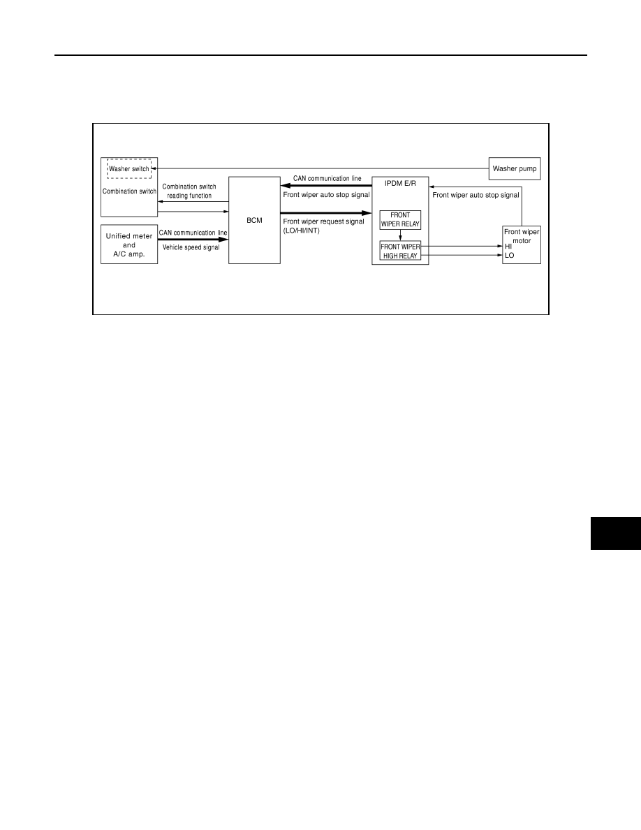
System Diagram
INFOID:0000000003591516
System Description
INFOID:0000000003591517
OUTLINE
The front wiper is controlled by each function of BCM and IPDM E/R.
Control by BCM
• Combination switch reading function
• Front wiper control function
Control by IPDM E/R
• Front wiper control function
• Relay control function
FRONT WIPER BASIC OPERATION
• BCM detects the combination switch condition by the combination switch reading function.
• BCM transmits the front wiper request signal to IPDM E/R with CAN communication depending on each
operating condition of the front wiper.
• IPDM E/R turns ON/OFF the integrated front wiper relay and the front wiper high relay according to the front
wiper request signal. IPDM E/R provides the power supply to operate the front wiper HI/LO operation.
FRONT WIPER LO OPERATION
• BCM transmits the front wiper request signal (LO) to IPDM E/R with CAN communication according to the
front wiper LO operating condition.
Front wiper LO operating condition
- Ignition switch ON
- Front wiper switch LO or front wiper switch MIST (while pressing)
• IPDM E/R turns ON the integrated front wiper relay according to the front wiper request signal (LO).
FRONT WIPER HI OPERATION
• BCM transmits the front wiper request signal (HI) to IPDM E/R with CAN communication according to the
front wiper HI operating condition.
Front wiper HI operating condition
- Ignition switch ON
- Front wiper switch HI
• IPDM E/R turns ON the integrated front wiper relay and the front wiper high relay according to the front wiper
request signal (HI).
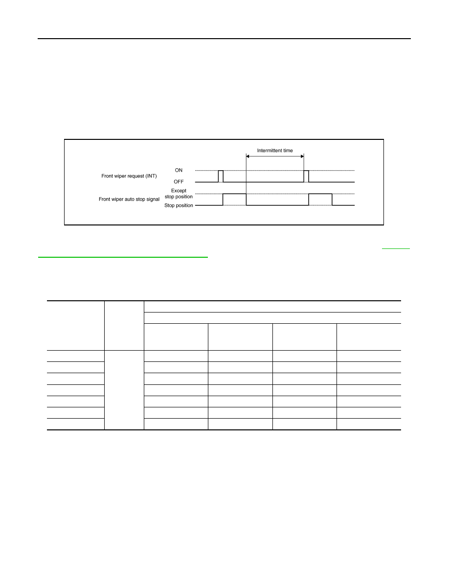
FRONT WIPER INT OPERATION
JPLIA0020GB
WW-6
< FUNCTION DIAGNOSIS >
FRONT WIPER AND WASHER SYSTEM
• BCM transmits the front wiper request signal (INT) to IPDM E/R with CAN communication depending on the
front wiper INT operating condition and intermittent operation delay interval according to the wiper intermit-
tent dial position.
Front wiper INT operating condition
- Ignition switch ON
- Front wiper switch INT
• IPDM E/R turns ON the integrated front wiper relay so that the front wiper is operated only once according to
the front wiper request signal (INT).
• BCM detects stop position/except stop position of the front wiper motor according to the front wiper auto stop
signal received from IPDM E/R with CAN communication.
• BCM transmits the front wiper request signal (INT) again after the intermittent operation delay interval.
NOTE:
Factory setting of the front wiper intermittent operation is the operation without vehicle speed. Front wiper
intermittent operation can be set to the operation with vehicle speed by CONSULT-III. Refer to
"WIPER : CONSULT-III Function (BCM - WIPER)"
Front wiper intermittent operation with vehicle speed
• BCM calculates the intermittent operation delay interval from the following
- Vehicle speed signal (received from the unified meter and A/C amp. with CAN communication)
- Wiper intermittent dial position
*: When without vehicle speed setting
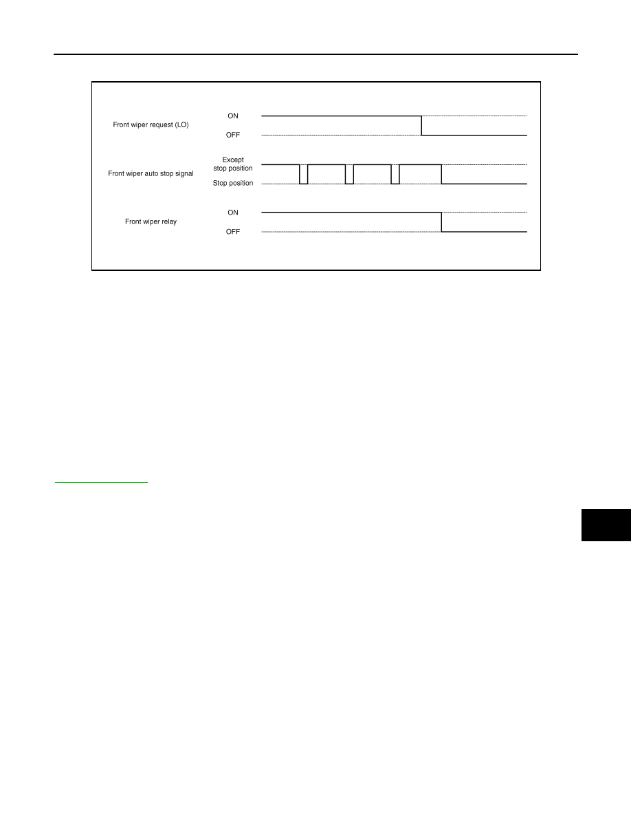
FRONT WIPER AUTO STOP OPERATION
• BCM stops transmitting the front wiper request signal when the front wiper switch is turned OFF.
• IPDM E/R detects the front wiper auto stop signal from the front wiper motor and detects the front wiper
motor position (stop position/except stop position).
Wiper intermittent
dial position
Intermittent
operation
interval
Intermittent operation delay Interval (s)
Vehicle speed
Vehicle stopped or
less than 5 km/h (3.1
MPH)
5 km/h (3.1MPH) or
more or less than
35km/h (21.7 MPH)
35 km/h (21.7 MPH)
or more or less than
65km/h (40.4 MPH)*
65 km/h (40.4MPH)
or more
1
Short
↑
↓
Long
0.8
0.6
0.4
0.24
2
4
3
2
1.2
3
10
7.5
5
3
4
16
12
8
4.8
5
24
18
12
7.2
6
32
24
16
9.6
7
42
31.5
21
12.6
JPLIA0094GB
FRONT WIPER AND WASHER SYSTEM
WW-7
< FUNCTION DIAGNOSIS >
C
D
E
F
G
H
I
J
K
M
A
B
WW
N
O
P
• When the front wiper request signal is stopped, IPDM E/R turns ON the front wiper relay until the front wiper
motor returns to the stop position.
NOTE:
• BCM stops the transmitting of the front wiper request signal when the ignition switch OFF.
• IPDM E/R turns the front wiper relay OFF when the ignition switch OFF.
FRONT WIPER OPERATION LINKED WITH WASHER
• BCM transmits the front wiper request signal (LO) to IPDM E/R with CAN communication according to the
washer linked operating condition of the front wiper.
• BCM transmits the front wiper request signal (LO) so that the front wiper operates approximately 2 times
when the front washer switch OFF is detected.
Washer linked operating condition of front wiper
- Ignition switch ON
- Front washer switch ON (0.4 second or more)
• IPDM E/R turns ON the integrated front wiper relay according to the front wiper request signal (LO).
• The washer pump is grounded through the combination switch when the front washer switch ON.
FRONT WIPER FAIL
−
SAFE OPERATION
When the front wiper auto stop circuit is malfunctioning, IPDM E/R performs the fail-safe function. Refer to
.
JPLIA0095GB
Нет комментариевНе стесняйтесь поделиться с нами вашим ценным мнением.
Текст