Infiniti EX35. Manual — part 471
DLK-98
< COMPONENT DIAGNOSIS >
[INTELLIGENT KEY SYSTEM]
KEY SLOT ILLUMINATION
KEY SLOT ILLUMINATION
Description
INFOID:0000000003728930
Blinks when Intelligent Key insertion is required.
Component Function Check
INFOID:0000000003728931
1.
CHECK FUNCTION
Check key slot illumination (“KEY SLOT ILLUMI”) Active Test mode.
Is the inspection result normal?
YES
>> Key slot function is OK.
NO
>> Refer to
.
Diagnosis Procedure
INFOID:0000000003728932
1.
CHECK FUSE
1.
Turn ignition switch OFF.
2.
Check 10 A fuse, [No.9, located in fuse block (J/B)].
Is fuse fusing?
YES
>> Replace the blown fuse after repairing the affected circuit if a fuse is blown.
NO
>> GO TO 2.
2.
CHECK KEY SLOT ILLUMINATION OUTPUT SIGNAL
Check voltage between key slot harness connector and ground.
Is the inspection result normal?
YES
>> GO TO 3.
NO
>> GO TO 4.
3.
CHECK KEY SLOT CIRCUIT
1.
Disconnect BCM and key slot connector.
2.
Check continuity between BCM harness connector and key slot harness connector.
3.
Check continuity between BCM harness connector and ground.
Is the inspection result normal?
YES
>> Replace BCM. Refer to
BCS-84, "Removal and Installation"
NO
>> Repair or replace harness.
4.
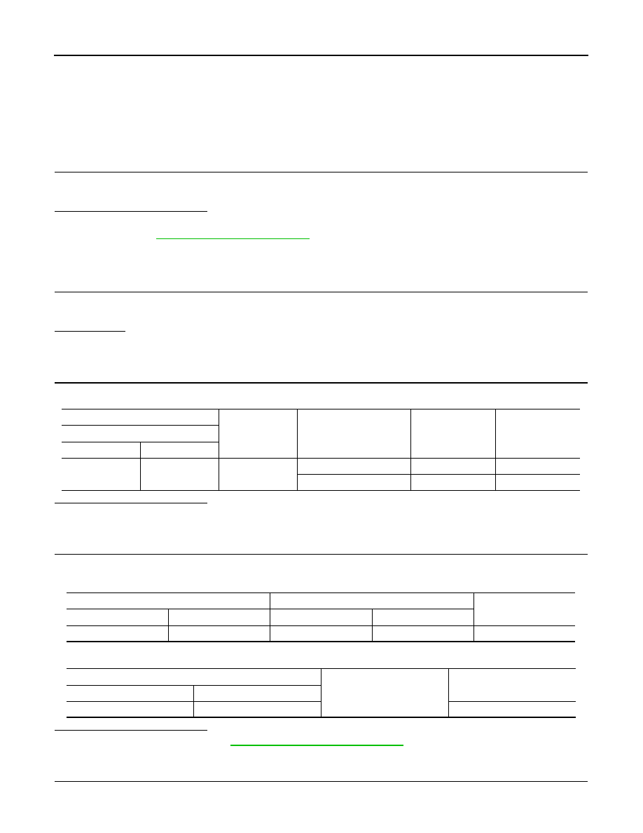
CHECK KEY SLOT POWER SUPPLY CIRCUIT
1.
Disconnect key slot connector.
(+)
(–)
Condition
Key slot
illumination
Voltage (V)
(Approx.)
Key slot
Connector
Terminal
M22
6
Ground
Intelligent Key inserted
OFF
Battery voltage
Intelligent Key removed
ON
0
BCM
Key slot
Continuity
Connector
Terminal
Connector
Terminal
M122
92
M22
6
Existed
BCM
Ground
Continuity
Connector
Terminal
M122
92
Not existed
KEY SLOT ILLUMINATION
DLK-99
< COMPONENT DIAGNOSIS >
[INTELLIGENT KEY SYSTEM]
C
D
E
F
G
H
I
J
L
M
A
B
DLK
N
O
P
2.
Check voltage between key slot harness connector and ground.
Is the inspection result normal?
YES
>> GO TO 5.
NO
>> Repair or replace harness.
5.
CHECK KEY SLOT GROUND CIRCUIT
Check continuity between key slot harness connector and ground.
Is the inspection result normal?
YES
>> GO TO 6.
NO
>> Repair or replace harness.
6.
CHECK KEY SLOT
DLK-99, "Component Inspection"
Is the inspection result normal?
YES
>> GO TO 7.
NO
>> Replace key slot. Refer to
DLK-262, "Removal and Installation"
7.
CHECK INTERMITTENT INCIDENT
GI-38, "Intermittent Incident"
.
>> INSPECTION END
Component Inspection
INFOID:0000000003728933
1.
CHECK KEY SLOT ILLUMINATION
1.
Turn ignition switch OFF.
2.
Disconnect key slot connector.
3.
Connect battery power supply to key slot terminals 5 and 6, and check the operation.
Is the inspection result normal?
YES
>> INSPECTION END
NO
>> Replace key slot. Refer to
DLK-262, "Removal and Installation"
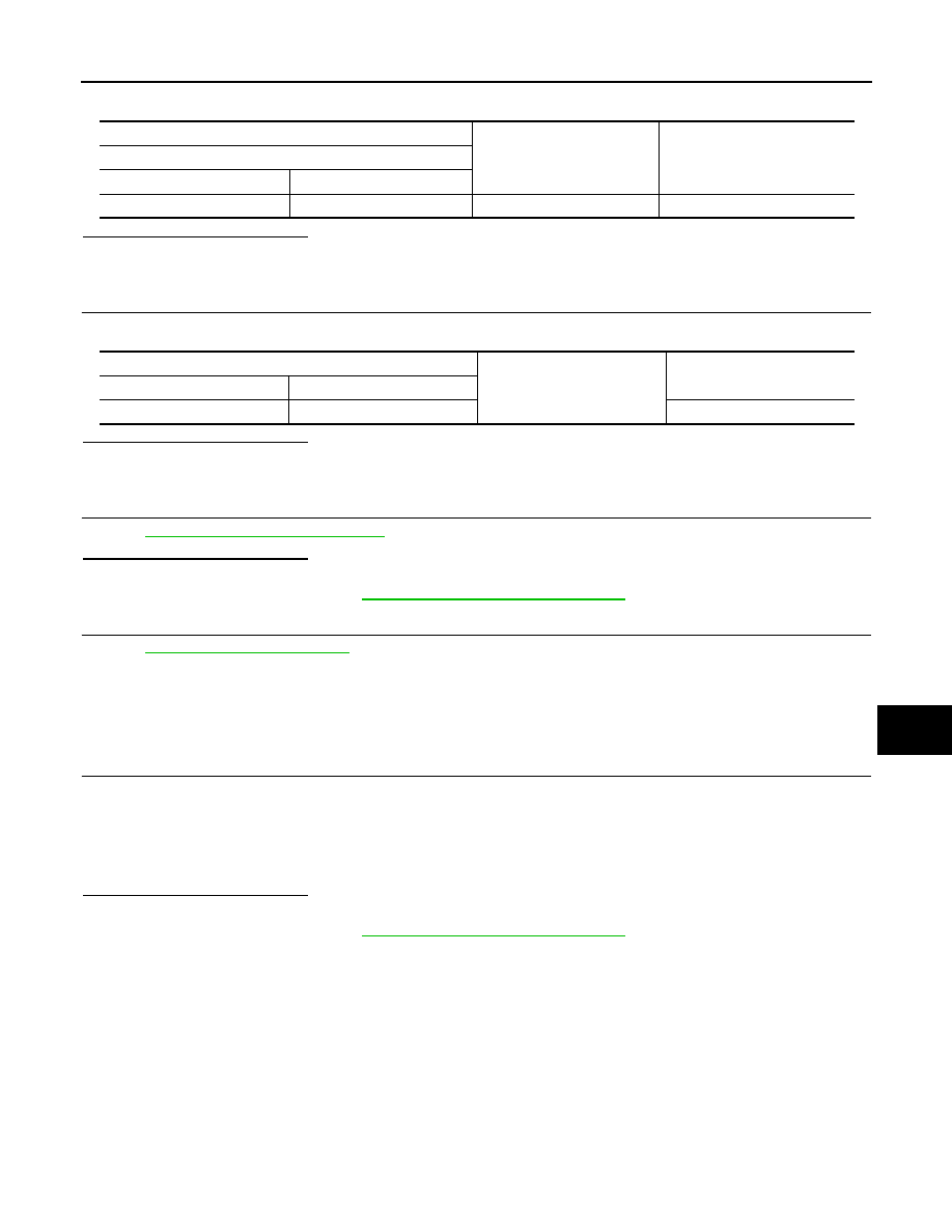
(+)
(–)
Voltage (V)
(Approx.)
Key slot
Connector
Terminal
M22
5
Ground
Battery voltage
Key slot
Ground
Continuity
Connector
Terminal
M22
7
Existed
5 (BAT+) - 6 (BAT-)
: Key slot illuminates
DLK-100
< COMPONENT DIAGNOSIS >
[INTELLIGENT KEY SYSTEM]
HORN FUNCTION
HORN FUNCTION
Description
INFOID:0000000003728934
Perform answer-back for each operation with horn.
Component Function Check
INFOID:0000000003728935
1.
CHECK FUNCTION
1.
Select “HORN” in “ACTIVE TEST” mode with CONSULT-III.
2.
Check the horn (high/low) operation.
Is the operation normal?
YES
>> Horn function is OK.
NO
>> Refer to
DLK-100, "Diagnosis Procedure"
Diagnosis Procedure
INFOID:0000000003728936
1.
CHECK HORN SWITCH
Check horn function with horn switch
Do the horns sound?
YES
>> GO TO 2.
NO
>> Refer to
HRN-2, "Wiring Diagram - HORN -"
.
2.
CHECK HORN RELAY POWER SUPPLY
1.
Turn ignition switch ON.
2.
Perform “ACTIVE TEST” (“HORN”) with CONSULT-Ill.
3.
Check voltage between malfunctioning horn relay harness connector and ground.
Is the inspection result normal?
YES
>> GO TO 4.
NO
>> GO TO 3.
3.
CHECK HORN RELAY CIRCUIT
1.
Turn ignition switch OFF.
2.
Disconnect IPDM E/R connector and horn relay connector.
3.
Check continuity between IPDM E/R harness connector and malfunctioning horn relay harness connector.
4.
Check continuity between driver seat control unit harness connector and ground.
Test item
Description
HORN
ON
Horn relay
ON (for 20 ms)
(+)
(–)
Test item
Voltage (V)
(Approx.)
Horn relay
Ground
Connector
Terminal
E11
Low
1
HORN
ON
Battery voltage
→
0
→
Battery voltage
E18
High
3
Other than above
Battery voltage
IPDM E/R
Horn relay
Continuity
Connector
Terminal
Connector
Terminal
E6
44
E11
1
Existed
45
E18
3
HORN FUNCTION
DLK-101
< COMPONENT DIAGNOSIS >
[INTELLIGENT KEY SYSTEM]
C
D
E
F
G
H
I
J
L
M
A
B
DLK
N
O
P
Is the inspection result normal?
YES
>> Replace IPDM E/R. Refer to
PCS-34, "Removal and Installation"
.
NO
>> Repair or replace harness.
4.
CHECK INTERMITTENT INCIDENT
GI-38, "Intermittent Incident"
.
Is the inspection result normal?
>> INSPECTION END
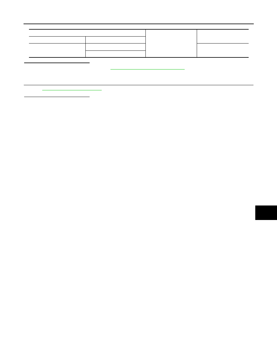
IPDM E/R
Ground
Continuity
Connector
Terminal
E6
44
Not existed
45
Нет комментариевНе стесняйтесь поделиться с нами вашим ценным мнением.
Текст