Infiniti EX35. Manual — part 1298

SEC-88
< COMPONENT DIAGNOSIS >
[INTELLIGENT KEY SYSTEM]
B2612 STEERING STATUS
YES
>> GO TO 10.
NO
>> Repair or replace harness or connector.
6.
CHECK BCM OUTPUT SIGNAL
1.
Turn ignition switch OFF.
2.
Disconnect steering lock unit connector and IPDM E/R connector E5.
3.
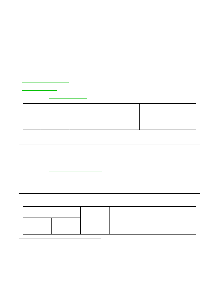
Check voltage between steering lock unit harness connector and ground.
Is the inspection result normal?
YES
>> GO TO 8.
NO
>> GO TO 7.
7.
CHECK STEERING LOCK UNIT CIRCUIT-3
1.
Disconnect BCM connector M122.
2.
Check continuity between steering lock unit harness connector and BCM harness connector.
3.
Check continuity between steering lock unit harness connector and ground.
Is the inspection result normal?
YES
>> GO TO 10.
NO
>> Repair or replace harness or connector.
8.
CHECK IPDM E/R OUTPUT SIGNAL
1.
Connect IPDM E/R connector.
2.
Disconnect BCM connector M122.
3.
Check voltage between steering lock unit harness connector and ground.
Is the inspection result normal?
YES
>> Replace steering lock unit.
NO
>> GO TO 9.
9.
CHECK STEERING LOCK UNIT CIRCUIT-4
1.
Disconnect IPDM E/R connector E5.
2.
Check continuity between steering lock unit harness connector and IPDM E/R harness connector.
3.
Check continuity between steering lock unit harness connector and ground.
(+)
(–)
Voltage (V)
(Approx.)
Steering lock unit
Connector
Terminal
M40
3
Ground
Battery voltage
Steering lock unit
BCM
Continuity
Connector
Terminal
Connector
Terminal
M40
3
M122
97
Existed
Steering lock unit
Ground
Continuity
Connector
Terminal
M40
3
Not existed
(+)
(–)
Voltage (V)
(Approx.)
Steering lock unit
Connector
Terminal
M40
3
Ground
Battery voltage
Steering lock unit
IPDM E/R
Continuity
Connector
Terminal
Connector
Terminal
M40
3
E5
32
Existed

B2612 STEERING STATUS
SEC-89
< COMPONENT DIAGNOSIS >
[INTELLIGENT KEY SYSTEM]
C
D
E
F
G
H
I
J
L
M
A
B
SEC
N
O
P
Is the inspection result normal?
YES
>> GO TO 10.
NO
>> Repair or replace harness or connector.
10.
CHECK INTERMITTENT INCIDENT
GI-38, "Intermittent Incident"
.
>> INSPECTION END
Steering lock unit
Ground
Continuity
Connector
Terminal
M40
3
Not existed
SEC-90
< COMPONENT DIAGNOSIS >
[INTELLIGENT KEY SYSTEM]
B2617 STARTER RELAY CIRCUIT
B2617 STARTER RELAY CIRCUIT
Description
INFOID:0000000003586594
Located in IPDM E/R, it runs the starter motor. The starter relay is turned ON by the BCM when the ignition
switch is in START position. IPDM E/R transmits the starter relay ON signal to BCM via CAN communication.
DTC Logic
INFOID:0000000003586595
DTC DETECTION LOGIC
NOTE:
• If DTC B2617 is displayed with DTC U1000, first perform the trouble diagnosis for DTC U1000. Refer to
.
• If DTC B2617 is displayed with DTC U1010, first perform the trouble diagnosis for DTC U1010. Refer to
.
• If DTC B2617 is displayed with DTC B2611, first perform the trouble diagnosis for DTC B2611. Refer to
.
• If DTC B2617 is displayed with DTC B210E for IPDM E/R, first perform the trouble diagnosis for DTC
DTC CONFIRMATION PROCEDURE
1.
PERFORM DTC CONFIRMATION PROCEDURE
1.
Turn ignition switch ON under the following conditions and wait for at least 1 second.
-
Selector lever is in the P or N position.
-
Do not depress brake pedal.
2.
Check “Self diagnostic result” with CONSULT-III.
Is DTC detected?
YES
>> Go to
NO
>> INSPECTION END
Diagnosis Procedure
INFOID:0000000003586596
1.
CHECK STARTER RELAY
1.
Turn ignition switch ON.
2.
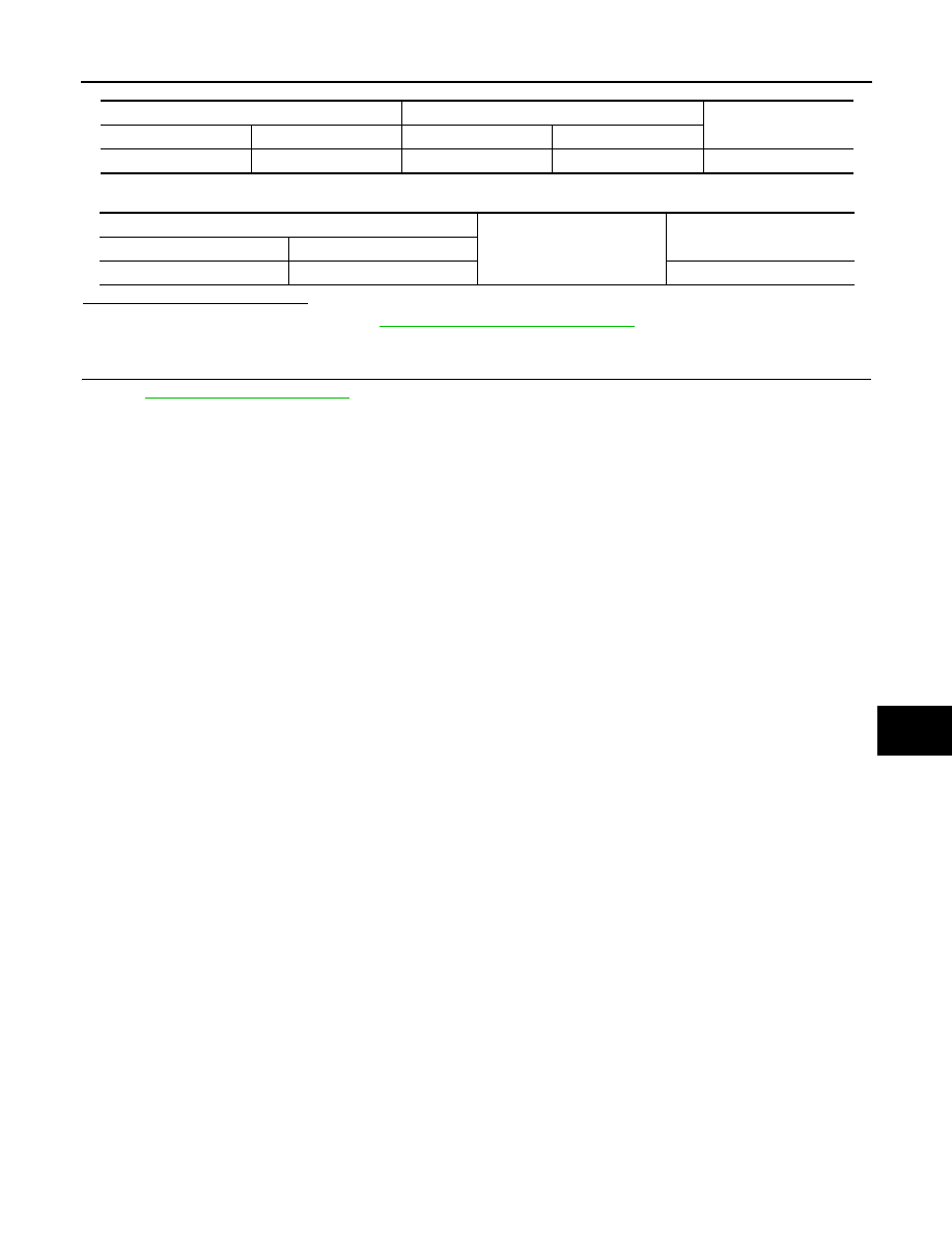
Check voltage between BCM harness connector and ground.
Is the measurement value within the specification.
YES
>> GO TO 3.
NO
>> GO TO 2.
2.
CHECK STARTER RELAY CIRCUIT
1.
Turn ignition switch OFF.
2.
Disconnect BCM connector M121 and IPDM E/R connector E6.
3.
Check continuity between IPDM E/R harness connector and BCM harness connector.
DTC No.
Trouble diagnosis
name
DTC detecting condition
Possible cause
B2617
STARTER RELAY
CIRCUIT
An immediate operation of starter relay is request-
ed by BCM, but there is no response for more than
1 second
• Harness or connectors
(Starter relay circuit is open or short-
ed.)
• IPDM E/R
(+)
(–)
Condition
Voltage (V)
(Approx.)
BCM
Connector
Terminal
M121
52
Ground
Selector lever
N or P position
Battery voltage
Other than above
0
B2617 STARTER RELAY CIRCUIT
SEC-91
< COMPONENT DIAGNOSIS >
[INTELLIGENT KEY SYSTEM]
C
D
E
F
G
H
I
J
L
M
A
B
SEC
N
O
P
4.
Check continuity between IPDM E/R harness connector and ground.
Is the inspection result normal?
YES
>> Replace IPDM E/R. Refer to
PCS-34, "Removal and Installation"
.
NO
>> Repair or replace harness or connector.
3.
CHECK INTERMITTENT INCIDENT
GI-38, "Intermittent Incident"
.
>> INSPECTION END
IPDM E/R
BCM
Continuity
Connector
Terminal
Connector
Terminal
E6
46
M121
52
Existed
IPDM E/R
Ground
Continuity
Connector
Terminal
E6
46
Not existed
Нет комментариевНе стесняйтесь поделиться с нами вашим ценным мнением.
Текст