Infiniti EX35. Manual — part 290
BCS
BODY CONTROL SYSTEM
BCS-7
< FUNCTION DIAGNOSIS >
C
D
E
F
G
H
I
J
K
L
B
A
O
P
N
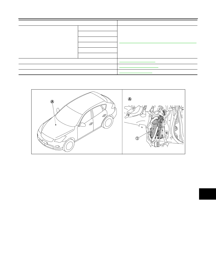
Component Parts Location
INFOID:0000000003137905
Intelligent Key system/engine start system
Door lock unlock function
DLK-15, "INTELLIGENT KEY SYSTEM : System Diagram"
Remote keyless function
Back door open function
Warning function
Key reminder function
Engine start function
Power window system
Retained accessory power (RAP) system
Tire pressure monitor system (TPMS) - AIR PRESSURE MONITOR
System
Reference
1.
BCM
A.
Dash side lower (passenger side)
JPMIA0938ZZ
BCS-8
< FUNCTION DIAGNOSIS >
COMBINATION SWITCH READING SYSTEM
COMBINATION SWITCH READING SYSTEM
System Diagram
INFOID:0000000003528880
System Description
INFOID:0000000003528881
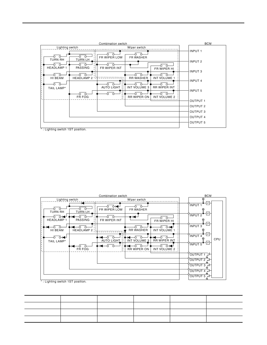
OUTLINE
• BCM reads the status of the combination switch (light, turn signal, wiper and washer) and recognizes the
status of each switch.
• BCM is a combination of 5 output terminals (OUTPUT 1 - 5) and 5 input terminals (INPUT 1 - 5). It reads a
maximum of 20 switch status.
COMBINATION SWITCH MATRIX
Combination switch circuit
Combination switch INPUT-OUTPUT system list
JPMIA0901GB
System
OUTPUT 1
OUTPUT 2
OUTPUT 3
OUTPUT 4
OUTPUT 5
INPUT 1
—
FR WASHER
FR WIPER LOW
TURN LH
TURN RH
INPUT 2
FR WIPER HI
—
FR WIPER INT
PASSING
HEADLAMP 1
INPUT 3
INT VOLUME 1
RR WASHER
—
HEADLAMP 2
HI BEAM
JPMIA0902GB
BCS
COMBINATION SWITCH READING SYSTEM
BCS-9
< FUNCTION DIAGNOSIS >
C
D
E
F
G
H
I
J
K
L
B
A
O
P
N
NOTE:
Headlamp has a dual system switch.
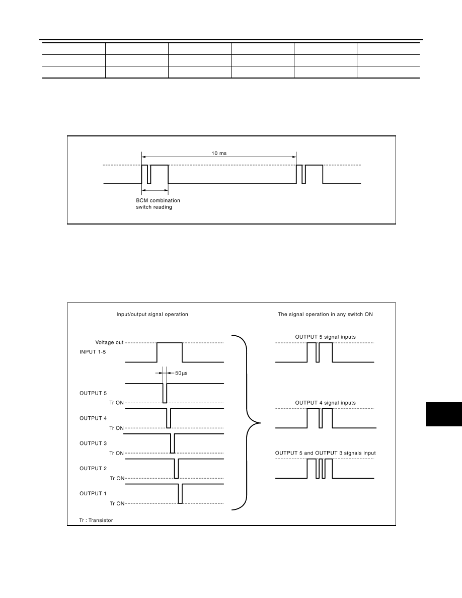
COMBINATION SWITCH READING FUNCTION
Description
• BCM reads the status of the combination switch at 10 ms interval normally.
NOTE:
BCM reads the status of the combination switch at 60 ms interval when BCM is controlled at low power con-
sumption mode.
• BCM operates as follows and judges the status of the combination switch.
- INPUT 1 - 5 outputs the voltage waveforms of 5 systems simultaneously.
- It operates the transistor on OUTPUT side in the following order: OUTPUT 5
→
4
→
3
→
2
→
1.
- The voltage waveform of INPUT corresponding to the formed circuit changes according to the operation of
the transistor on OUTPUT side if any (1 or more) switches are ON.
- It reads this change of the voltage as the status signal of the combination switch.
Operation Example
In the following operation example, the combination of the status signals of the combination switch is replaced
as follows: INPUT 1 - 5 to “1 - 5” and OUTPUT 1 - 5 to “A - E”.
Example 1: When a switch (TURN RH switch) is turned ON
INPUT 4
RR WIPER INT
INT VOLUME 3
AUTO LIGHT
—
TAIL LAMP
INPUT 5
INT VOLUME 2
RR WIPER ON
—
FR FOG
—
System
OUTPUT 1
OUTPUT 2
OUTPUT 3
OUTPUT 4
OUTPUT 5
JPMIA0067GB
JPMIA0068GB

BCS-10
< FUNCTION DIAGNOSIS >
COMBINATION SWITCH READING SYSTEM
• The circuit between INPUT 1 and OUTPUT 5 is formed when the TURN RH switch is turned ON.
• BCM detects the combination switch status signal “1E” when the signal of OUTPUT 5 is input to INPUT 1.
• BCM judges that the TURN RH switch is ON when the signal “1E” is detected.
Example 2: When some switches (turn RH switch, front wiper LO switch) are turned ON
• The circuits between INPUT 1 and OUTPUT 5 and between INPUT 1 and OUTPUT 3 are formed when the
TURN RH switch and FR WIPER LOW switch are turned ON.
• BCM detects the combination switch status signal “1CE” when the signals of OUTPUT 3 and OUTPUT 5 are
input to INPUT 1.
• BCM judges that the TURN RH switch and FR WIPER LOW switch are ON when the signal “1CE” is
detected.
WIPER INTERMITTENT DIAL POSITION SETTING (FRONT WIPER INTERMITTENT OPERATION)
BCM judges the wiper intermittent dial 1 - 7 by the status of INT VOLUME 1, 2 and 3 switches.
JPMIA0903GB
JPMIA0904GB
Нет комментариевНе стесняйтесь поделиться с нами вашим ценным мнением.
Текст