Infiniti EX35. Manual — part 156

AV
MULTI AV SYSTEM SYMPTOMS
AV-405
< SYMPTOM DIAGNOSIS >
[BOSE AUDIO WITHOUT NAVIGATION]
C
D
E
F
G
H
I
J
K
L
M
B
A
O
P
RELATED TO iPod
®
Trouble diagnosis chart by symptom
Connect another iPod
®
and check if the symptom is reproduced or not. If the symptom is reproduced, diag-
nose the vehicle. If no malfunction is detected, replace the iPod harness.
NOTE:
It is unable to check that between iPod
®
and iPod harness.
Audio sound is not heard.
No sound from all speakers.
• BOSE amp. power supply and ground circuit.
Refer to
AV-220, "BOSE AMP. : Diagnosis Procedure"
.
• Amp. ON signal circuit
Sound is not heard from woofer.
• Woofer power supply and ground circuit.
• Sound signal woofer circuit between BOSE amp. and
woofer.
• Woofer ON signal circuit between BOSE amp. and
woofer.
Sound is not heard from center speaker.
Sound signal center speaker circuit.
Sound is heard only from specific places
(RH front, RH rear, LH front and LH rear).
Sound signal circuit of malfunctioning system.
It does not change to “Driver's
Audio Stage” mode.
—
Mode change signal circuit.
Refer to
Satellite radio is not received.
“ANTENNA” is not displayed even when
the channel is turned to 0 in Satellite ra-
dio mode.
Perform the following inspection procedure.
1.
Check satellite radio antenna mounting nut for
looseness.
NOTE:
Tightening torque: 6.5 N·m (0.66 kg-m, 58 in-lb.)
2.
Visually check for satellite radio antenna feeder.
3.
Replace the satellite radio antenna.
Refer to
.
4.
Replace the satellite radio tuner.
Refer to
.
“ANTENNA” is displayed when the chan-
nel is turned to 0 in Satellite radio mode.
Perform the following inspection procedure.
1.
Check the connection between Satellite radio tuner
and antenna feeder.
2.
Check the connection between Satellite radio anten-
na and antenna feeder.
3.
Check Antenna feeder for open circuit.
4.
Replace the satellite radio antenna.
Refer to
.
5.
Replace the satellite radio tuner.
Refer to
.
The sound of Satellite radio is
not heard.
Other audio sounds are normal.
Satellite radio sound signal circuit between AV control unit
and satellite radio tuner.
It does not change to Satellite
radio mode.
There is malfunction in the CONSULT-III
self-diagnosis result.
Perform CONSULT-III self-diagnosis.
Refer to
AV-201, "CONSULT-III Function (MULTI AV)"
.
AM/FM radio is not received.
Other audio sounds are normal.
• Antenna amp. ON signal circuit.
• Antenna feeder.
Symptoms
Check items
Possible malfunction location / Action to take
Symptoms
Check items
Possible malfunction location / Action to take
The sound of iPod
®
is not
heard.
Other audio sounds are normal.
• iPod sound signal circuit between AV control unit and
iPod adapter.
• iPod sound signal circuit between iPod
®
and iPod
adapter.
It does not change to iPod
mode.
There is malfunction in the CONSULT-III
self-diagnosis.
Perform CONSULT-III self-diagnosis.
Refer to
AV-201, "CONSULT-III Function (MULTI AV)"
.
“iPod is not connected” is dis-
played when it comes to iPod
mode.
Connected to iPod
®
.
iPod connection recognition signal circuit between iPod
®
and iPod adapter.
AV-406
< SYMPTOM DIAGNOSIS >
[BOSE AUDIO WITHOUT NAVIGATION]
MULTI AV SYSTEM SYMPTOMS
RELATED TO STEERING SWITCH
Trouble diagnosis chart by symptom
RELATED TO AUX
NOTE:
Check that there is no malfunction of AUX equipment main body before performing a diagnosis.
Trouble diagnosis chart by symptom
RELATED TO REAR VIEW MONITOR
iPod
®
cannot charge the bat-
tery.
—
iPod battery charge circuit between iPod
®
and iPod
adapter.
The title of music file in the iP-
od
®
is not indicated.
—
Communication circuit between iPod
®
and iPod adapter.
Accessing the iPod
®
is unavail-
able from the vehicle.
Symptoms
Probable malfunction location
None of the steering switch operations work.
Steering switch signal GND circuit.
Refer to
Only specified switch cannot be operated.
Steering switch.
“SOURCE”, “MENU UP”, “MENU DOWN”, “
” switches
of steering switch are not operated.
Steering switch signal A circuit.
Refer to
”VOL UP“, “VOL DOWN”, “
” switches of steering switch
are not operated.
Steering switch signal B circuit.
Refer to
Symptoms
Check items
Possible malfunction location / Action to take
Symptoms
Check items
Probable malfunction location
No voice sound is heard when
AUX mode is selected.
Voice sound is heard when other modes
are selected.
AUX sound signal circuits malfunction between auxiliary
input jacks and AV control unit.
Image is not displayed when
AUX mode is selected.
—
• AUX image signal circuit malfunction between auxilia-
ry input jacks and AV control unit.
Refer to
• Horizontal synchronizing (HP) signal circuit malfunc-
tion between AV control unit and display unit.
Refer to
• Vertical synchronizing (VP) signal circuit malfunction
between AV control unit and display unit.
Refer to
• RGB area (YS) signal circuit malfunction between AV
control unit and display unit.
Refer to
Camera image is normal (with rear view
monitor)
AUX image signal circuit malfunction between auxiliary
input jacks and AV control unit.
Refer to
Camera image is not displayed. (with rear
view monitor)
• Horizontal synchronizing (HP) signal circuit malfunc-
tion between AV control unit and display unit.
Refer to
• Vertical synchronizing (VP) signal circuit malfunction
between AV control unit and display unit.
Refer to
• RGB area (YS) signal circuit malfunction between AV
control unit and display unit.
Refer to
It does not change from AUX
mode to other modes.
—
• Vertical synchronizing (VP) signal circuit malfunction
between AV control unit and display unit.
Refer to
• Horizontal synchronizing (HP) signal circuit malfunc-
tion between AV control unit and display unit.
Refer to

AV
MULTI AV SYSTEM SYMPTOMS
AV-407
< SYMPTOM DIAGNOSIS >
[BOSE AUDIO WITHOUT NAVIGATION]
C
D
E
F
G
H
I
J
K
L
M
B
A
O
P
Trouble diagnosis chart by symptom
Symptoms
Check items
Probable malfunction location
Camera image is not displayed
(displayed in black and nothing
can be displayed)
AUX image is not displayed.
• Horizontal synchronizing (HP) signal circuit malfunc-
tion between AV control unit and display unit.
Refer to
• Vertical synchronizing (VP) signal circuit malfunction
between AV control unit and display unit.
Refer to
Camera image is not shown.
(Guiding line is displayed.)
—
• Camera image signal circuit between camera control
unit and rear view camera.
• Rear view camera power supply circuit.
Camera image is not displayed.
(Only warning message under
area is displayed.)
There is malfunction in the CONSULT-III
self-diagnosis result.
Perform detected DTC self-diagnosis.
Refer to
AV-201, "CONSULT-III Function (MULTI AV)"
AUX image is normal.
Camera image signal circuit malfunction between cam-
era control unit and AV control unit.
Refer to
AUX image is not displayed.
RGB area (YS) signal circuit malfunction between AV
control unit and display unit.
Refer to
Select “Camera Cont.” of “Confirmation/
Adjustment” mode, Reverse Sensor is not
turned ON at “Connection Confirmation”.
Reverse signal circuit (camera control unit).
Camera image is rolling.
AUX image is also rolling.
Vertical synchronizing (VP) signal circuit malfunction be-
tween AV control unit and display unit.
Refer to
Camera image does not switch.
Malfunction of self-diagnosis result is indi-
cated.
Camera-connection recognition signal circuit
Refer to
AV-201, "CONSULT-III Function (MULTI AV)"
Malfunction of self-diagnosis result is not
indicated.
Reverse signal circuit (AV control unit).
The predicted course line dis-
play is malfunctioning.
—

AV-408
< SYMPTOM DIAGNOSIS >
[BOSE AUDIO WITHOUT NAVIGATION]
NORMAL OPERATING CONDITION
NORMAL OPERATING CONDITION
Description
INFOID:0000000003508745
Vehicle operation information, refer to Owner's Manual.
BASIC OPERATIONS
RELATED TO VOICE RECOGNITION
Related to telephone
The system should respond correctly to all voice commands without difficulty. If problems are encountered, try
the following solutions.
Where the solutions are listed by number, try each solution in turn, starting with number 1, until the problem is
resolves.
RELATED TO AUDIO
• The majority of the audio malfunctions are the result of outside causes (bad CD/cassette, electromagnetic
interference, etc.). Check the symptoms below to diagnose the malfunction.
• The vehicle itself can be a source of noise if noise prevention parts or electrical equipment is malfunctioning.
Check if noise is caused and/or changed by engine speed, ignition switch turned to each position, and oper-
ation of each piece of electrical equipment, and then determine the cause.
NOTE:
• CD-R is not guaranteed to play because they can contain compressed audio (MP3, WMA) or could be incor-
rectly mastered by the customer on a computer.
• Check if the CDs carry the Compact Disc Logo. If not, the disc is not mastered to the “red book” Compact
Disc Standard and may not play.
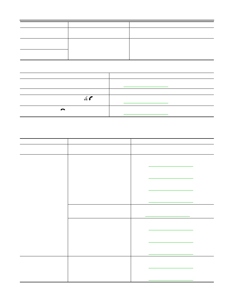
Symptom
Possible cause
Possible solution
No image is displayed.
The brightness is at the lowest setting.
Adjust the brightness of the display.
The system is in the video mode.
Push <DISC> to change the mode.
The display is turned off.
Push <Day/Night> to turn on the display.
The screen is too dim. The move-
ment is slow.
The temperature in the interior of the vehicle is low.
Wait until the interior of the vehicle has
warmed up.
Some pixels in the display are dark-
er or brighter than others.
This condition is an inherent characteristic of liquid
crystal displays.
This is not a malfunction.
Some menu items cannot be se-
lected.
Some menu items become unavailable while the ve-
hicle is driven.
Park the vehicle in a safe location, and
then operate the multi AV system.
Symptom
Solution
System fails to interpret the com-
mand correctly.
1. Ensure that the command is valid.
2. Ensure that the command is spoken after the tone.
3. Speak clearly without pausing between words and at level appropriate to the ambient noise lev-
el in the vehicle.
4. Ensure that the ambient noise level is not excessive (for example, windows open or defroster
on).
NOTE:
If it is too noisy to use the phone, it is likely that the voice commands will be recognized.
5. If more than one command was said at a time, try saying the commands separately.
6. If the system consistently fails to recognize commands, the voice training procedure should be
carried out to improve the recognition response for the speaker. See “Speaker adaptation (SA)
mode” earlier in this section. Refer to “OWNER’S MANUAL”.
The system consistently selects
the wrong voicetag
1. Ensure that the phone book entry name requested matches what was originally stored. This
can be confirmed by using the “List Names” command.
2. Replace one of the names being confused with a new name.
Нет комментариевНе стесняйтесь поделиться с нами вашим ценным мнением.
Текст