Infiniti EX35. Manual — part 155
AV
TEL ADAPTER UNIT
AV-401
< ECU DIAGNOSIS >
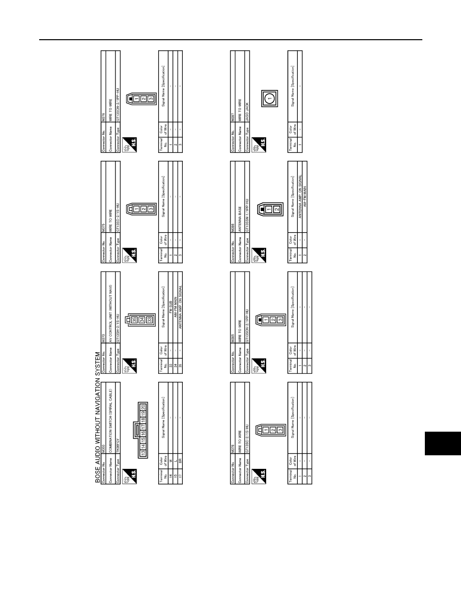
[BOSE AUDIO WITHOUT NAVIGATION]
C
D
E
F
G
H
I
J
K
L
M
B
A
O
P
JCNWM0759GB
AV-402
< ECU DIAGNOSIS >
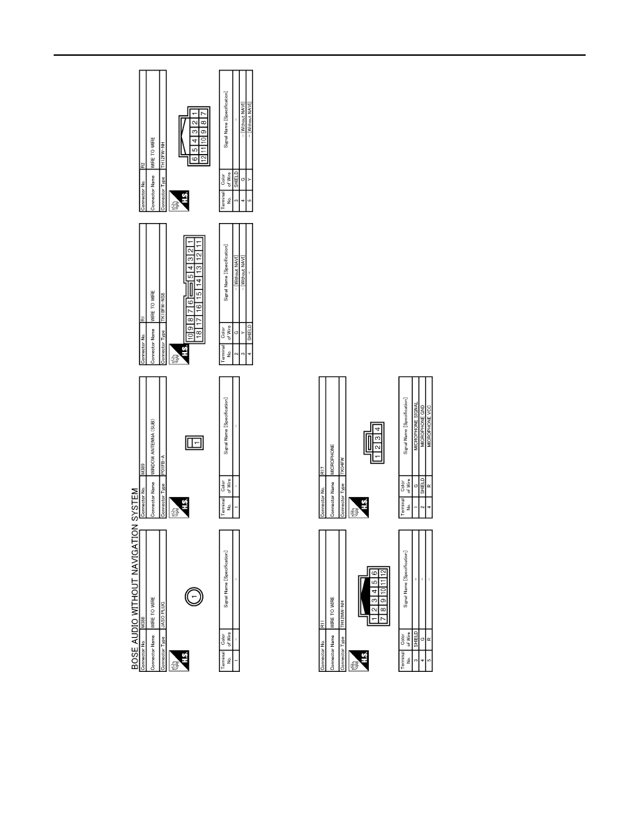
[BOSE AUDIO WITHOUT NAVIGATION]
TEL ADAPTER UNIT
JCNWM0760GB
AV
MULTI AV SYSTEM SYMPTOMS
AV-403
< SYMPTOM DIAGNOSIS >
[BOSE AUDIO WITHOUT NAVIGATION]
C
D
E
F
G
H
I
J
K
L
M
B
A
O
P
SYMPTOM DIAGNOSIS
MULTI AV SYSTEM SYMPTOMS
Symptom Table
INFOID:0000000003508744
OPERATION
RELATED TO HANDS-FREE PHONE
Basic Inspection
• Check that the cellular phone is corresponding type (Bluetooth
®
correspond) when the hands-free related
malfunction vehicle is in service before performing a diagnosis.
• There is a case that malfunction occurs due to the version change of the phone type, etc. even though it is a
corresponding type. Therefore, confirm it by changing the cellular phone to another corresponding type
phone, and check that it operates normally. It is necessary to distinguish whether the cause is the vehicle or
cellular phone.
Simple check for Bluetooth
®
communication
• If cellular phone and AV control unit cannot be connected with Bluetooth
®
communication, following proce-
dure allows the technician to judge which device has malfunction.
1.
Turn on a cellular phone, not connecting Bluetooth
®
communication.
2.
Start CONSULT-III, then start Windows
®
.
3.
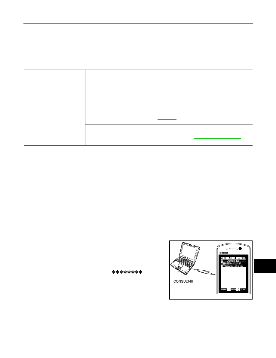
Set CONSULT-III near a cellular phone.
4.
When operated Bluetooth
®
registration by cellular phone, check
if CONSULT-III
*
would be displayed on the device name.
(If other Bluetooth
®
device is located near cellular phone, a
name of the device would be displayed also.)
NOTE:
*:Displayed device name is “NISSAN-
”.
• If no device name is displayed, cellular phone is malfunctioning.
Repair the cellular phone first, then perform diagnosis.
• If CONSULT-III is displayed on device name, cellular phone is nor-
mal. Perform diagnosis as per the following table.
On board self-diagnosis of hands-free phone system
Always perform the on board self-diagnosis at first after completing the basic inspection when the malfunction
is detected on the hands-free phone system. Narrow down possible causes using the Diagnosis Chart if there
is no malfunction in the on board self-diagnosis.
Trouble diagnosis chart by symptom
Symptoms
Check items
Possible malfunction location / Action to take
Multifunction switch and preset
switch operation does not work.
• All switches cannot be operated.
• “MULTI AV” is displayed on system
selection screen when the CON-
SULT-III is started.
• Multifunction switch power supply and ground circuit.
• AV communication circuit between AV control unit and
multifunction switch.
Perform CONSULT-III self-diagnosis.
Refer to
AV-201, "CONSULT-III Function (MULTI AV)"
.
• All switches cannot be operated.
• “MULTI AV” is not displayed on sys-
tem selection screen when the CON-
SULT-III is started.
AV control unit power supply and ground circuit malfunc-
tion. Refer to
AV-218, "AV CONTROL UNIT : Diagnosis
.
Only specified switch cannot be operat-
ed.
Multifunction switch or preset switch malfunction. Per-
form multifunction switch and preset switch self-diagno-
sis function. Refer to
.
JPNIA0441GB
AV-404
< SYMPTOM DIAGNOSIS >
[BOSE AUDIO WITHOUT NAVIGATION]
MULTI AV SYSTEM SYMPTOMS
RELATED TO RGB IMAGE
Trouble diagnosis chart by symptom
RELATED TO AUDIO
Trouble diagnosis chart by symptom
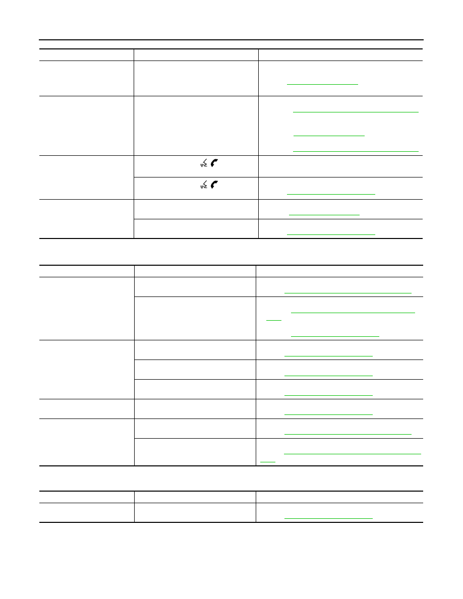
Symptoms
Check items
Probable malfunction location
Does not recognize cellular
phone connection. (No connec-
tion is displayed on the display
at the guide.)
Repeat the registration of cellular phone.
TEL adapter unit malfunction.
Refer to
Hands-free phone cannot be
established.
Both the reception and the speech cannot
be performed.
• Perform CONSULT-III self-diagnosis.
Refer to
AV-201, "CONSULT-III Function (MULTI AV)"
.
• No malfunction.
TEL adapter unit malfunction.
Refer to
• Malfunction is detected.
Refer to
AV-201, "CONSULT-III Function (MULTI AV)"
.
The other party's voice cannot
be heard by hands-free phone.
The operation of the “
” switch can
be performed.
TEL voice signal circuit malfunction between TEL adapt-
er unit and AV control unit.
The operation of the “
” switch can-
not be performed.
Control signal circuit.
Refer to
.
Originating sound is not heard
by the other party with hands-
free phone communication.
Sound operation function is normal.
TEL adapter unit.
Refer to
.
Sound operation function does not work.
Microphone signal circuit.
Refer to
.
Symptoms
Check items
Possible malfunction location / Action to take
RGB image is not shown.
There is malfunction in the CONSULT-III
self-diagnosis result.
Perform CONSULT-III self-diagnosis.
Refer to
AV-201, "CONSULT-III Function (MULTI AV)"
.
There is no malfunction in CONSULT-III
self-diagnosis results.
• Display unit power supply and ground circuit.
AV-218, "DISPLAY UNIT : Diagnosis Proce-
.
• Vertical synchronizing (VP) signal circuit.
Color of RGB image is not
proper.
Light blue (Cyan) tint.
RGB signal (R: red) circuit.
Refer to
.
Purple (Magenta) tint.
RGB signal (G: green) circuit.
Refer to
.
Screen looks yellowish.
RGB signal (B: blue) circuit.
Refer to
.
RGB screen is rolling.
—
RGB synchronizing signal circuit.
Refer to
.
Fuel economy display is mal-
functioning.
There is malfunction in the CONSULT-III
self-diagnosis result.
Perform CONSULT-III self-diagnosis.
Refer to
AV-201, "CONSULT-III Function (MULTI AV)"
.
There is no malfunction in CONSULT-III
self-diagnosis results.
Ignition signal circuit malfunction.
Refer to
AV-218, "AV CONTROL UNIT : Diagnosis Proce-
Symptoms
Check items
Possible malfunction location / Action to take
The CD cannot be removed.
—
Disk eject signal circuit.
Refer to
.
Нет комментариевНе стесняйтесь поделиться с нами вашим ценным мнением.
Текст