Infiniti EX35. Manual — part 542
DLN-118
< DISASSEMBLY AND ASSEMBLY >
[FRONT FINAL DRIVE: F160A]
DIFFERENTIAL ASSEMBLY
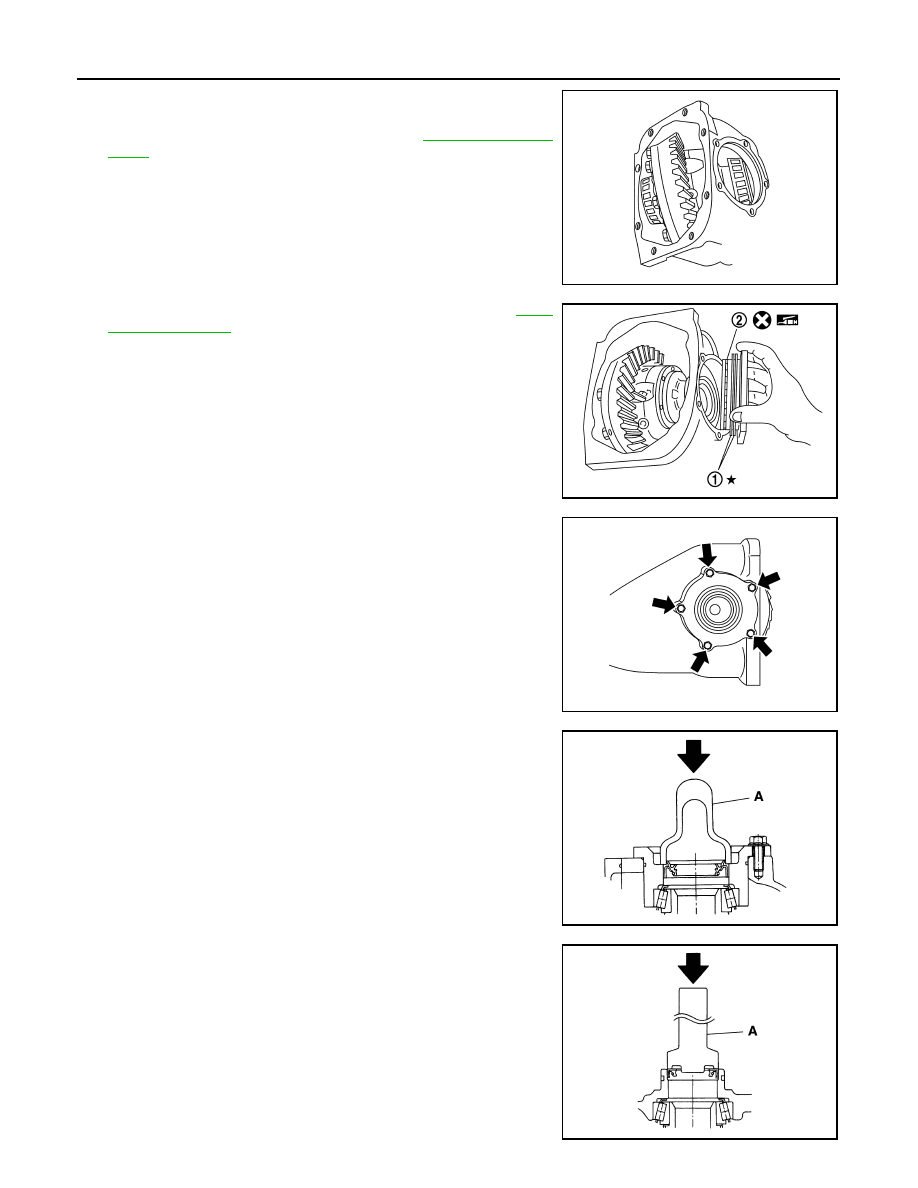
13. Place the differential case assembly into gear carrier.
14. Measure side bearing preload. If necessary, select the appropri-
ate side bearing adjusting shim. Refer to
15. Install selected side bearing adjusting shim (1). Refer to
.
16. Apply multi-purpose grease to O-ring (2), and install it to side
retainer.
CAUTION:
Never reuse O-ring.
17. Install side retainer assembly to gear carrier.
18. Install side retainer mounting bolts.
19. Using the drift (A) [SST: ST33400001 (J-26082)], press-fit side
oil seal so that its surface comes face-to-face with the end sur-
face of the side retainer.
CAUTION:
• Never reuse oil seal.
• When installing, never incline oil seal.
• Apply multi-purpose grease onto oil seal lips, and gear oil
onto the circumference of oil seal.
20. Using the drift (A) [SST: KV38102100 (J-25803-01)], press-fit
side oil seal so that its surface comes face-to-face with the end
surface of gear carrier.
CAUTION:
• Never reuse oil seal.
• When installing, never incline oil seal.
• Apply multi-purpose grease onto oil seal lips, and gear oil
onto the circumference of oil seal.
21. Apply multi-purpose grease to O-ring, and install it to gear car-
rier.
CAUTION:
PDIA0671E
PDIA0813E
PDIA0669E
PDIA0787J
PDIA0788J

DIFFERENTIAL ASSEMBLY
DLN-119
< DISASSEMBLY AND ASSEMBLY >
[FRONT FINAL DRIVE: F160A]
C
E
F
G
H
I
J
K
L
M
A
B
DLN
N
O
P
Never reuse O-ring.
22. Check and adjust drive gear runout, tooth contact, drive gear to drive pinion backlash, and total preload
.
Recheck above items. Readjust as described above, if necessary.
23. Apply sealant (A) to mating surface of carrier cover.
• Use Genuine Silicone RTV or equivalent. Refer to
"Recommended Chemical Products and Sealants"
.
CAUTION:
Remove old sealant adhering to mounting surfaces. Also
remove any moisture, oil, or foreign material adhering to
application and mounting surfaces.
24. Install carrier cover on gear carrier and tighten mounting bolts.
25. Set breather connector angle (A) as shown in the figure.
Adjustment
INFOID:0000000003135798
TOTAL PRELOAD TORQUE
• Before inspection and adjustment, drain gear oil.
1.
Rotate drive pinion back and forth 2 to 3 times to check for unusual noise and rotation malfunction.
2.
Rotate drive pinion at least 20 times to check for smooth opera-
tion of the bearing.
3.
Measure total preload with preload gauge (A) [SST:
ST3127S000 (J-25765-A)].
NOTE:
Total preload torque = Pinion bearing preload torque + Side
bearing preload torque
PDIA0742E
SDIA1648E
: Vehicle front
A
: 0 – 30
°
PDIA0841J
Standard
Total preload torque
: Refer to
PDIA0792J
DLN-120
< DISASSEMBLY AND ASSEMBLY >
[FRONT FINAL DRIVE: F160A]
DIFFERENTIAL ASSEMBLY
• If measured value is out of the specification, disassemble it to check and adjust each part. Adjust the
pinion bearing preload and side bearing preload.
Adjust the pinion bearing preload first, then adjust the side bearing preload.
SIDE BEARING PRELOAD
• Before inspection and adjustment, drain gear oil.
1.
Remove carrier cover and side retainer. Refer to
2.
Make sure all parts are clean. Also, make sure the bearings are well lubricated with gear oil.
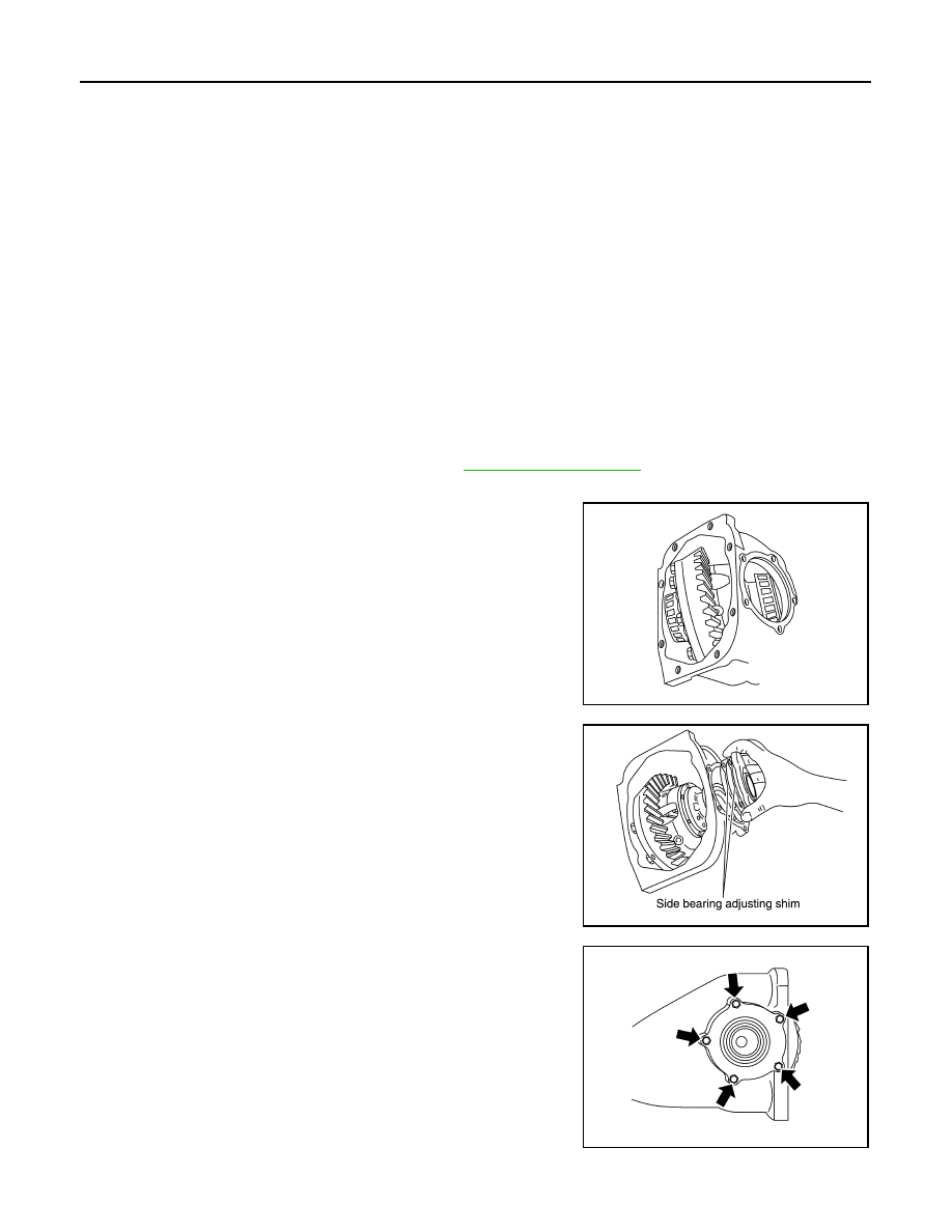
3.
Place the differential case assembly into gear carrier.
4.
Install side bearing adjusting shim before disassembling or shim
which thickness is the same as the one before disassembling.
5.
Install side retainer assembly to gear carrier.
CAUTION:
Never install O-ring.
6.
Install side retainer mounting bolts to the specified torque.
When the preload torque is large
On pinion bearings:
Decrease the drive pinion bearing adjusting washer and drive pinion
adjusting washer thickness.
On side bearings:
Increase the side bearing adjusting shim thickness. For select parts
refer to parts information.
When the preload torque is small
On pinion bearings:
Increase the drive pinion bearing adjusting washer and drive pinion
adjusting washer thickness.
On side bearings:
Decrease the side bearing adjusting shim thickness. For select parts
refer to parts information.
PDIA0671E
PDIA0678E
PDIA0669E

DIFFERENTIAL ASSEMBLY
DLN-121
< DISASSEMBLY AND ASSEMBLY >
[FRONT FINAL DRIVE: F160A]
C
E
F
G
H
I
J
K
L
M
A
B
DLN
N
O
P
7.
Measure the turning torque of the gear carrier at the drive gear
mounting bolts with a spring gauge [SST:
—
(J-8129)].
8.
If the turning torque is outside the specification, use a thicker/
thinner side bearing adjusting shim to adjust.
9.
Record the total amount of shim thickness required for the cor-
rect carrier side bearing preload.
DRIVE GEAR RUNOUT
1.
Remove carrier cover. Refer to
2.
Fit a dial indicator to the drive gear back face.
3.
Rotate the drive gear to measure runout.
• If the runout is outside of the repair limit, check drive gear
assembly condition; foreign material may be caught between
drive gear and differential case, or differential case or drive
gear may be deformed, etc.
CAUTION:
Replace drive gear and drive pinion gear as a set.
TOOTH CONTACT
Before inspection and adjustment, drain gear oil.
1.
Remove carrier cover. Refer to
2.
Apply red lead to drive gear.
CAUTION:
Apply red lead to both the faces of 3 to 4 gears at 4 loca-
tions evenly spaced on drive gear.
Specification
: 34.2 – 39.2 N (3.5 – 4.0 kg,
7.7 – 8.8 lb) of pulling force
at the drive gear bolt
SPD194A
If the turning torque is less than the specified range:
Decrease the side bearing adjusting shim thickness.
If the turning torque is greater than the specification:
Increase the side bearing adjusting shim thickness.
SPD772
Limit
Drive gear runout
: Refer to
SPD886
SPD357
Нет комментариевНе стесняйтесь поделиться с нами вашим ценным мнением.
Текст