Infiniti EX35. Manual — part 924

HAC-92
< COMPONENT DIAGNOSIS >
[AUTOMATIC AIR CONDITIONER]
AMBIENT SENSOR
Is the inspection result normal?
YES
>> GO TO 2.
NO
>> GO TO 4.
2.
CHECK CIRCUIT CONTINUITY BETWEEN AMBIENT SENSOR AND UNIFIED METER AND A/C AMP.
1.
Turn ignition switch OFF.
2.
Disconnect unified meter and A/C amp. connector.
3.
Check continuity between ambient sensor harness connector and unified meter and A/C amp. harness
connector.
Is the inspection result normal?
YES
>> GO TO 3.
NO
>> Repair harness or connector.
3.
CHECK AMBIENT SENSOR
Check ambient sensor. Refer to
HAC-92, "Component Inspection"
.
Is the inspection result normal?
YES
>> Replace unified meter and A/C amp.
NO
>> Replace ambient sensor.
4.
CHECK CIRCUIT CONTINUITY BETWEEN AMBIENT SENSOR AND UNIFIED METER AND A/C AMP.
1.
Turn ignition switch OFF.
2.
Disconnect unified meter and A/C amp. connector.
3.
Check continuity between ambient sensor harness connector and unified meter and A/C amp. harness
connector.
4.
Check continuity between ambient sensor harness connector and ground.
Is the inspection result normal?
YES
>> Replace unified meter and A/C amp.
NO
>> Repair harness or connector.
Component Inspection
INFOID:0000000003545629
1.
CHECK AMBIENT SENSOR
1.
Turn ignition switch OFF.
2.
Disconnect ambient sensor connector. Refer to
3.
Check resistance between ambient sensor terminals.
(+)
(
−
)
Voltage
Ambient sensor
—
Connector
Terminal
E76
1
Ground
Approx. 5 V
Ambient sensor
Unified meter and A/C amp.
Continuity
Connector
Terminal
Connector
Terminal
E76
2
M67
61
Existed
Ambient sensor
Unified meter and A/C amp.
Continuity
Connector
Terminal
Connector
Terminal
E76
1
M67
45
Existed
Ambient sensor
—
Continuity
Connector
Terminal
E76
1
Ground
Not existed

AMBIENT SENSOR
HAC-93
< COMPONENT DIAGNOSIS >
[AUTOMATIC AIR CONDITIONER]
C
D
E
F
G
H
J
K
L
M
A
B
HAC
N
O
P
Is the inspection result normal?
YES
>> END.
NO
>> Replace ambient sensor.
Terminal
Condition
Resistance k
Ω
Temperature
°
C (
°
F)
1
2
−
15 (5)
12.73
−
10 (14)
9.92
−
5 (23)
7.80
0 (32)
6.19
5 (41)
4.95
10 (50)
3.99
15 (59)
3.24
20 (68)
2.65
25 (77)
2.19
30 (86)
1.81
35 (95)
1.51
40 (104)
1.27
45 (113)
1.07
HAC-94
< COMPONENT DIAGNOSIS >
[AUTOMATIC AIR CONDITIONER]
IN-VEHICLE SENSOR
IN-VEHICLE SENSOR
Description
INFOID:0000000003545630
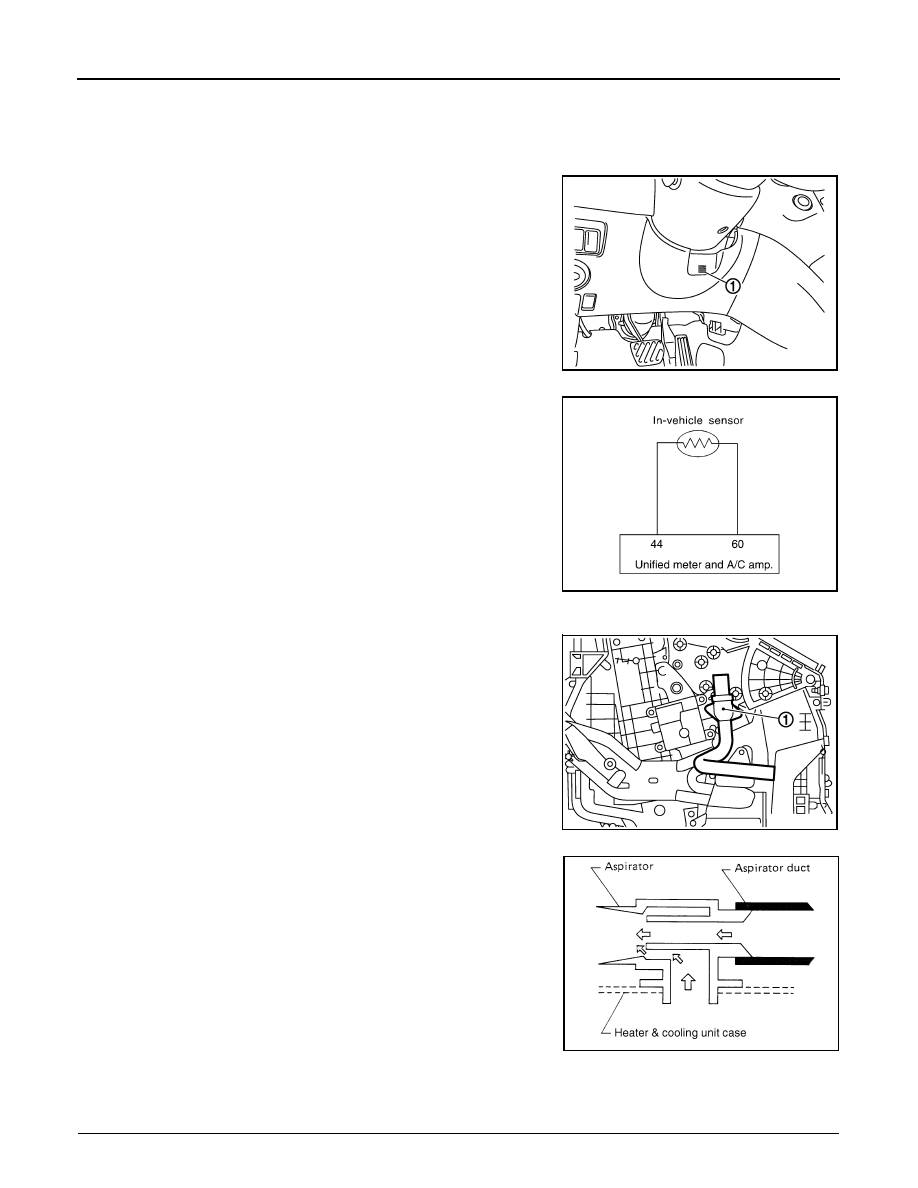
In-vehicle Sensor
The in-vehicle sensor (1) is located on instrument driver lower panel.
It converts variations in compartment air temperature drawn from the
aspirator into a resistance value. It is then input into the unified meter
and A/C amp.
In-vehicle Sensor Circuit
Aspirator
The aspirator (1) is located on driver’s side of heater & cooling unit
assembly. It produces vacuum pressure due to air discharged from
the heater & cooling unit assembly, continuously taking compartment
air in the aspirator.
Component Function Check
INFOID:0000000003545631
1.
PERFORM SELF-DIAGNOSIS STEP-2
JSIIA1071ZZ
RJIA4094E
JSIIA0100ZZ
RJIA1804E

IN-VEHICLE SENSOR
HAC-95
< COMPONENT DIAGNOSIS >
[AUTOMATIC AIR CONDITIONER]
C
D
E
F
G
H
J
K
L
M
A
B
HAC
N
O
P
Perform self-diagnosis STEP-2. Refer to
HAC-57, "WITHOUT LEFT AND RIGHT VENTILATION TEMPERA-
TURE SEPARATELY CONTROL SYSTEM : Diagnosis Description"
(Without left and right ventilation tempera-
ture separately control system) or
HAC-63, "WITH LEFT AND RIGHT VENTILATION TEMPERATURE
SEPARATELY CONTROL SYSTEM : Diagnosis Description"
(With left and right ventilation temperature sepa-
rately control system), see Nos. 1 to 2.
22 or –22 is displayed.
YES
>> Go to Diagnosis Procedure. Refer to
.
NO
>> END.
Diagnosis Procedure
INFOID:0000000003545632
1.
CHECK VOLTAGE BETWEEN IN-VEHICLE SENSOR AND GROUND
1.
Disconnect in-vehicle sensor connector.
2.
Turn ignition switch ON.
3.
Check voltage between in-vehicle sensor harness connector and ground.
Is the inspection result normal?
YES
>> GO TO 2.
NO
>> GO TO 4.
2.
CHECK CIRCUIT CONTINUITY BETWEEN IN-VEHICLE SENSOR AND UNIFIED METER AND A/C AMP.
1.
Turn ignition switch OFF.
2.
Disconnect unified meter and A/C amp. connector.
3.
Check continuity between in-vehicle sensor harness connector and unified meter and A/C amp. harness
connector.
Is the inspection result normal?
YES
>> GO TO 3.
NO
>> Repair harness or connector.
3.
CHECK IN-VEHICLE SENSOR
Check in-vehicle sensor. Refer to
HAC-96, "Component Inspection"
Is the inspection result normal?
YES
>> Replace unified meter and A/C amp.
NO
>> Replace in-vehicle sensor.
4.
CHECK CIRCUIT CONTINUITY BETWEEN IN-VEHICLE SENSOR AND UNIFIED METER AND A/C AMP.
1.
Turn ignition switch OFF.
2.
Disconnect unified meter and A/C amp. connector.
3.
Check continuity between in-vehicle sensor harness connector and unified meter and A/C amp. harness
connector.
4.
Check continuity between in-vehicle sensor harness connector and ground.
(+)
(
−
)
Voltage
In-vehicle sensor
—
Connector
Terminal
M61
1
Ground
Approx. 5 V
In-vehicle sensor
Unified meter and A/C amp.
Continuity
Connector
Terminal
Connector
Terminal
M61
2
M67
60
Existed
In-vehicle sensor
Unified meter and A/C amp.
Continuity
Connector
Terminal
Connector
Terminal
M61
1
M67
44
Existed
Нет комментариевНе стесняйтесь поделиться с нами вашим ценным мнением.
Текст