Infiniti EX35. Manual — part 923

HAC-88
< COMPONENT DIAGNOSIS >
[AUTOMATIC AIR CONDITIONER]
MAGNET CLUTCH
MAGNET CLUTCH
Description
INFOID:0000000003545623
Magnet clutch drives a compressor, by a signal of IPDM E/R.
Component Function Check
INFOID:0000000003545624
1.
CONFIRM SYMPTOM BY PERFORMING THE FOLLOWING OPERATIONAL CHECK
1.
Press AUTO switch.
2.
Display should indicate AUTO. Confirm that the magnet clutch engages (sound or visual inspection). (Dis-
charge air and blower speed depend on ambient, in-vehicle and set temperatures.)
Does the magnet clutch operate?
YES
>> END.
NO
>> Go to Diagnosis Procedure. Refer to
.
Diagnosis Procedure
INFOID:0000000003545625
1.
PERFORM SELF-DIAGNOSIS STEP-2
Perform self-diagnosis STEP-2. Refer to
HAC-57, "WITHOUT LEFT AND RIGHT VENTILATION TEMPERA-
TURE SEPARATELY CONTROL SYSTEM : Diagnosis Description"
(Without left and right ventilation tempera-
ture separately control system) or
HAC-63, "WITH LEFT AND RIGHT VENTILATION TEMPERATURE
SEPARATELY CONTROL SYSTEM : Diagnosis Description"
(With left and right ventilation temperature sepa-
rately control system), see Nos. 1 to 2.
Is there any malfunction displayed?
YES
>> Go to appropriate malfunctioning sensor circuit. Refer to
HAC-57, "WITHOUT LEFT AND RIGHT
VENTILATION TEMPERATURE SEPARATELY CONTROL SYSTEM : Diagnosis Description"
(Without left and right ventilation temperature separately control system) or
AND RIGHT VENTILATION TEMPERATURE SEPARATELY CONTROL SYSTEM : Diagnosis
Description"
(With left and right ventilation temperature separately control system), see to No. 11.
NO
>> GO TO 2.
2.
PERFORM SELF-DIAGNOSIS STEP-4
Perform self-diagnosis STEP-4. Refer to
HAC-57, "WITHOUT LEFT AND RIGHT VENTILATION TEMPERA-
TURE SEPARATELY CONTROL SYSTEM : Diagnosis Description"
(Without left and right ventilation tempera-
ture separately control system) or
HAC-63, "WITH LEFT AND RIGHT VENTILATION TEMPERATURE
SEPARATELY CONTROL SYSTEM : Diagnosis Description"
(With left and right ventilation temperature sepa-
rately control system), see Nos. 1 to 5.
Is it operated normally?
YES
>> END.
NO
>> GO TO 3.
3.
PERFORM IPDM E/R AUTO ACTIVE TEST
Perform IPDM E/R auto active test. Refer to
PCS-11, "Diagnosis Description"
Does the magnet clutch operate?
YES
>> •
WITH CONSULT-III: GO TO 6.
•
WITHOUT CONSULT-III: GO TO 7.
NO
>> Check 10A fuse (No. 49, located in IPDM E/R), and GO TO 4.
4.
CHECK CIRCUIT CONTINUITY BETWEEN IPDM E/R AND COMPRESSOR
1.
Turn ignition switch OFF.
2.
Disconnect IPDM E/R connector and compressor connector.
3.
Check continuity between IPDM E/R harness connector and compressor harness connector.
IPDM E/R
Compressor
Continuity
Connector
Terminal
Connector
Terminal
E7
48
F43
1
Existed

MAGNET CLUTCH
HAC-89
< COMPONENT DIAGNOSIS >
[AUTOMATIC AIR CONDITIONER]
C
D
E
F
G
H
J
K
L
M
A
B
HAC
N
O
P
Is the inspection result normal?
YES
>> GO TO 5.
NO
>> Repair harness or connector.
5.
CHECK MAGNET CLUTCH CIRCUIT
Check for operation sound when applying battery voltage direct current to terminal.
Is the inspection result normal?
YES
>> 1.
Replace IPDM E/R.
2.
Refer to self-diagnosis procedure
HAC-57, "WITHOUT LEFT AND RIGHT VENTILATION
TEMPERATURE SEPARATELY CONTROL SYSTEM : Diagnosis Description"
(Without left
and right ventilation temperature separately control system) or
RIGHT VENTILATION TEMPERATURE SEPARATELY CONTROL SYSTEM : Diagnosis
Description"
(With left and right ventilation temperature separately control system) and per-
form self-diagnosis STEP-4. Confirm that magnet clutch operation normal.
NO
>> 1.
Replace compressor.
2.
Refer to self-diagnosis procedure
HAC-57, "WITHOUT LEFT AND RIGHT VENTILATION
TEMPERATURE SEPARATELY CONTROL SYSTEM : Diagnosis Description"
(Without left
and right ventilation temperature separately control system) or
RIGHT VENTILATION TEMPERATURE SEPARATELY CONTROL SYSTEM : Diagnosis
Description"
(With left and right ventilation temperature separately control system) and per-
form self-diagnosis STEP-4. Confirm that magnet clutch operation normal.
6.
CHECK ECM INPUT SIGNAL-1
Check A/C switch signal in “Data monitor”. Refer to
HAC-62, "WITHOUT LEFT AND RIGHT VENTILATION
TEMPERATURE SEPARATELY CONTROL SYSTEM : CONSULT-III Function"
.
Is the inspection result normal?
YES
>> GO TO 9.
NO
>> GO TO 7.
7.
CHECK REFRIGERANT PRESSURE SENSOR
WITH CONSULT-III
1.
Start the engine.
2.
Check voltage of refrigerant pressure sensor in “Data monitor”. Refer to
WITHOUT CONSULT-III
1.
Start the engine.
2.
Check voltage between ECM harness connector and ground.
Is the inspection result normal?
YES
>> •
WITH CONSULT-III: GO TO 8.
•
WITHOUT CONSULT-III: Repair harness or connector.
NO
>> Refer to
.
8.
CHECK ECM INPUT SIGNAL-2
Check blower fan motor switch signal in “Data monitor”. Refer to
HAC-62, "WITHOUT LEFT AND RIGHT
VENTILATION TEMPERATURE SEPARATELY CONTROL SYSTEM : CONSULT-III Function"
.
A/C SWITCH ON
: AIR COND SIG On
A/C SWITCH OFF
: AIR COND SIG Off
(+)
(
−
)
Condition
Voltage
ECM
—
connector
Terminal
M107
105
Ground
A/C switch: ON
(Blower motor operates.)
Approx. 1.0 - 4.0 V
FAN SWITCH ON
: HEATER FAN SW On
FAN SWITCH OFF
: HEATER FAN SW Off
HAC-90
< COMPONENT DIAGNOSIS >
[AUTOMATIC AIR CONDITIONER]
MAGNET CLUTCH
Is the inspection result normal?
YES
>> GO TO 9.
NO
>> Repair harness or connector.
9.
CHECK CAN COMMUNICATION
Check CAN communication. Refer to
LAN-18, "Trouble Diagnosis Flow Chart"
.
• ECM – IPDM E/R
• ECM – Unified meter and A/C amp.
Is the inspection result normal?
YES
>> Replace ECM.
NO
>> Repair or replace malfunctioning part(s).
AMBIENT SENSOR
HAC-91
< COMPONENT DIAGNOSIS >
[AUTOMATIC AIR CONDITIONER]
C
D
E
F
G
H
J
K
L
M
A
B
HAC
N
O
P
AMBIENT SENSOR
Description
INFOID:0000000003545626
COMPONENT DESCRIPTION
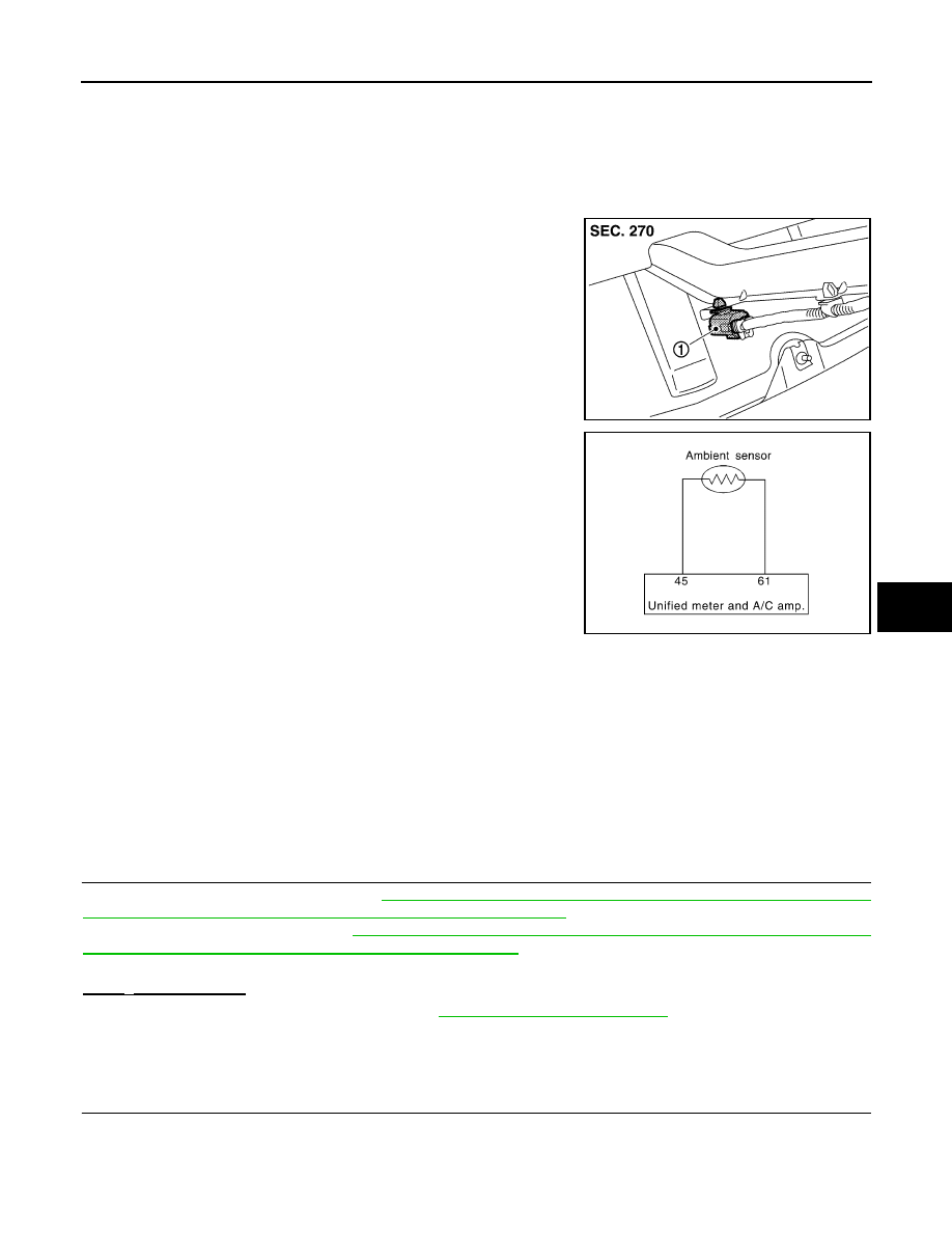
Ambient Sensor
The ambient sensor (1) is attached on the radiator core support (left
side). It detects ambient temperature and converts it into a resis-
tance value which is then input into the unified meter and A/C amp.
Ambient Sensor Circuit
AMBIENT TEMPERATURE INPUT PROCESS
The unified meter and A/C amp. equips a processing circuit for the ambient sensor input. However, when the
temperature detected by the ambient sensor increases quickly, the processing circuit retards the unified meter
and A/C amp. function. It only allows the unified meter and A/C amp. to recognize an ambient temperature
increase of 0.33
°
C (0.6
°
F) per 100 seconds.
As an example, consider stopping for a few minutes after high speed driving. Although the actual ambient tem-
perature has not changed, the temperature detected by the ambient sensor increases. This is because the
heat from the engine compartment can radiate to the front bumper area, location of the ambient sensor.
Component Function Check
INFOID:0000000003545627
1.
PERFORM SELF-DIAGNOSIS STEP-2
Perform self-diagnosis STEP-2. Refer to
HAC-57, "WITHOUT LEFT AND RIGHT VENTILATION TEMPERA-
TURE SEPARATELY CONTROL SYSTEM : Diagnosis Description"
(Without left and right ventilation tempera-
ture separately control system) or
HAC-63, "WITH LEFT AND RIGHT VENTILATION TEMPERATURE
SEPARATELY CONTROL SYSTEM : Diagnosis Description"
(With left and right ventilation temperature sepa-
rately control system), see Nos. 1 to 2.
21 or
−
21 is displayed.
YES
>> Go to Diagnosis Procedure. Refer to
.
NO
>> END.
Diagnosis Procedure
INFOID:0000000003545628
1.
CHECK VOLTAGE BETWEEN AMBIENT SENSOR AND GROUND
1.
Disconnect ambient sensor connector.
2.
Turn ignition switch ON.
3.
Check voltage between ambient sensor harness connector and ground.
JPIIA0643ZZ
RJIA4088E
Нет комментариевНе стесняйтесь поделиться с нами вашим ценным мнением.
Текст