Infiniti EX35. Manual — part 1423
TM-80
< COMPONENT DIAGNOSIS >
[5AT: RE5R05A]
P1762 DIRECT CLUTCH SOLENOID VALVE
P1762 DIRECT CLUTCH SOLENOID VALVE
Description
INFOID:0000000003130541
• The direct clutch solenoid valve is controlled by the TCM in response to signals transmitted from the PNP
switch, vehicle speed sensor and accelerator pedal position sensor (throttle position sensor). Gears will then
be shifted to the optimum position.
• The direct clutch solenoid valve controls the direct clutch control valve in response to a signal transmitted
from the TCM.
DTC Logic
INFOID:0000000003130542
DTC DETECTION LOGIC
DTC CONFIRMATION PROCEDURE
CAUTION:
Always drive vehicle at a safe speed.
NOTE:
If “DTC CONFIRMATION PROCEDURE” has been previously performed, always turn ignition switch
OFF. Then wait at least 10 seconds before performing the next test.
1.
CHECK DTC DETECTION
With CONSULT-III
1.
Start the engine.
2.
Select “Data Monitor” mode for “TRANSMISSION”.
3.
Drive vehicle and maintain the following conditions for at least 5 consecutive seconds.
With GST
Follow the procedure “With CONSULT-III”.
Is “P1762 D/C SOLENOID/CIRC” detected?
YES
>> Go to
NO
>> Check intermittent incident. Refer to
GI-38, "Intermittent Incident"
.
Diagnosis Procedure
INFOID:0000000003130543
1.
CHECK TCM POWER SUPPLY AND GROUND CIRCUIT
Check TCM power supply and ground circuit. Refer to
.
Is the inspection result normal?
YES
>> Replace the control valve with TCM. Refer to
NO
>> Repair or replace damaged parts.
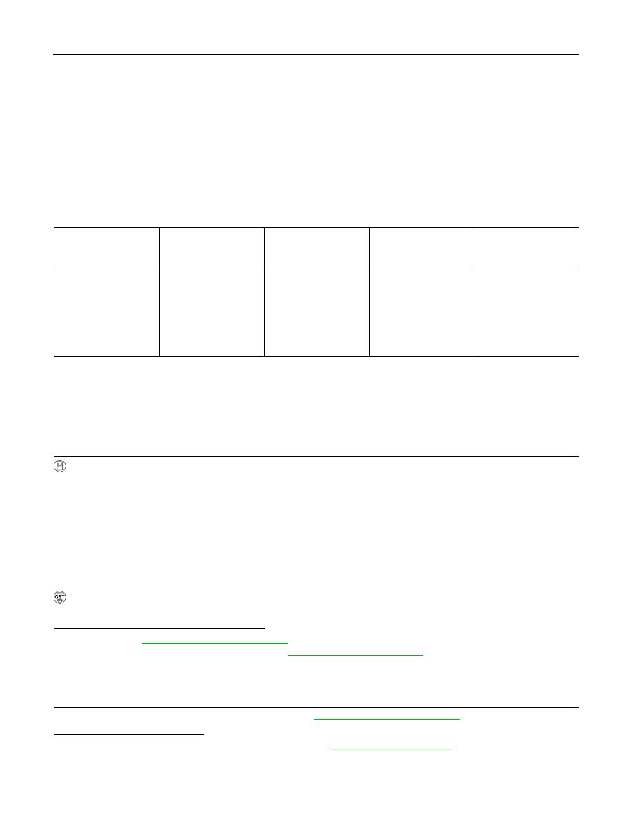
DTC
Item
(CONSULT-III screen
terms)
A/T CHECK indicator
lamp judgment flicker
Diagnostic item is de-
tected when...
Possible cause
P1762
D/C SOLENOID/CIRC
2nd
• Normal voltage not ap-
plied to solenoid due
to cut line, short, or the
like.
• TCM detects as irregu-
lar by comparing tar-
get value with monitor
value.
• Harness or connectors
(Solenoid circuit is
open or shorted.)
• Direct clutch solenoid
valve
ACCELE POSI
: 1.5/8 – 2.0/8
GEAR
: “1”
⇒
“2” (D/C ON/OFF)
SLCT LVR POSI
: “D” position
Driving location
: Driving the vehicle uphill (increased engine load) will help maintain the driving con-
ditions required for this test.
P1767 HIGH AND LOW REVERSE CLUTCH SOLENOID VALVE
TM-81
< COMPONENT DIAGNOSIS >
[5AT: RE5R05A]
C
E
F
G
H
I
J
K
L
M
A
B
TM
N
O
P
P1767 HIGH AND LOW REVERSE CLUTCH SOLENOID VALVE
Description
INFOID:0000000003130544
• The high and low reverse clutch solenoid valve is controlled by the TCM in response to signals transmitted
from the PNP switch, vehicle speed sensor and accelerator pedal position sensor (throttle position sensor).
Gears will then be shifted to the optimum position.
• The high and low reverse clutch solenoid valve controls the high and low reverse clutch control valve in
response to a signal transmitted from the TCM.
DTC Logic
INFOID:0000000003130545
DTC DETECTION LOGIC
DTC CONFIRMATION PROCEDURE
CAUTION:
Always drive vehicle at a safe speed.
NOTE:
If “DTC CONFIRMATION PROCEDURE” has been previously performed, always turn ignition switch
OFF. Then wait at least 10 seconds before performing the next test.
1.
CHECK DTC DETECTION
With CONSULT-III
1.
Start the engine.
2.
Select “Data Monitor” mode for “TRANSMISSION”.
3.
Drive vehicle and maintain the following conditions for at least 5 consecutive seconds.
With GST
Follow the procedure “With CONSULT-III”.
Is “P1767 HLR/C SOL/CIRC” detected?
YES
>> Go to
NO
>> Check intermittent incident. Refer to
GI-38, "Intermittent Incident"
.
Diagnosis Procedure
INFOID:0000000003130546
1.
CHECK TCM POWER SUPPLY AND GROUND CIRCUIT
Check TCM power supply and ground circuit. Refer to
Is the inspection result normal?
YES
>> Replace the control valve with TCM. Refer to
NO
>> Repair or replace damaged parts.
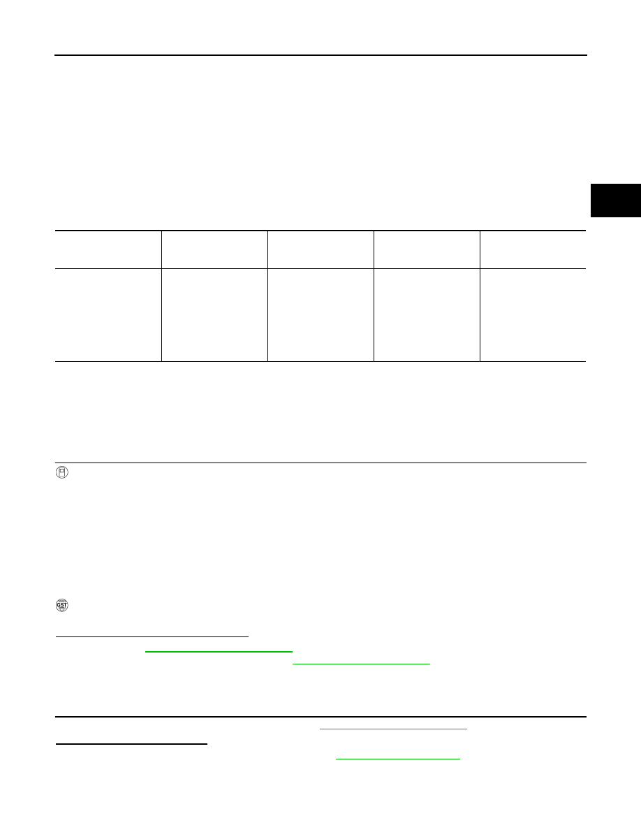
DTC
Item
(CONSULT-III screen
terms)
A/T CHECK indicator
lamp judgment flicker
Diagnostic item is de-
tected when...
Possible cause
P1767
HLR/C SOL/CIRC
8th
• Normal voltage not ap-
plied to solenoid due
to cut line, short, or the
like.
• TCM detects as irregu-
lar by comparing tar-
get value with monitor
value.
• Harness or connectors
(Solenoid circuit is
open or shorted.)
• High and low reverse
clutch solenoid valve
ACCELE POSI
: 1.5/8 – 2.0/8
GEAR
: “2”
⇒
“3” (HLR/C ON/OFF)
SLCT LVR POSI
: “D” position
Driving location
: Driving the vehicle uphill (increased engine load) will help maintain the driving
conditions required for this test.
TM-82
< COMPONENT DIAGNOSIS >
[5AT: RE5R05A]
P1772 LOW COAST BRAKE SOLENOID VALVE
P1772 LOW COAST BRAKE SOLENOID VALVE
Description
INFOID:0000000003130547
• The low coast brake solenoid valve is turned ON or OFF by the TCM in response to signals transmitted from
the PNP switch, vehicle speed sensor and accelerator pedal position sensor (throttle position sensor). Gears
will then be shifted to the optimum position.
• The low coast brake solenoid valve controls the low coast brake switching valve in response to a signal
transmitted from the TCM.
DTC Logic
INFOID:0000000003130548
DTC DETECTION LOGIC
DTC CONFIRMATION PROCEDURE
CAUTION:
Always drive vehicle at a safe speed.
NOTE:
If “DTC CONFIRMATION PROCEDURE” has been previously performed, always turn ignition switch
OFF. Then wait at least 10 seconds before performing the next test.
1.
CHECK DTC DETECTION
With CONSULT-III
1.
Start the engine.
2.
Select “Data Monitor” mode for “TRANSMISSION”.
3.
Drive vehicle and maintain the following conditions for at least 5 consecutive seconds.
With GST
Follow the procedure “With CONSULT-III”.
Is “P1772 LC/B SOLENOID/CIRC” detected?
YES
>> Go to
NO
>> Check intermittent incident. Refer to
GI-38, "Intermittent Incident"
.
Diagnosis Procedure
INFOID:0000000003130549
1.
CHECK TCM POWER SUPPLY AND GROUND CIRCUIT
Check TCM power supply and ground circuit. Refer to
.
Is the inspection result normal?
YES
>> Replace the control valve with TCM. Refer to
NO
>> Repair or replace damaged parts.
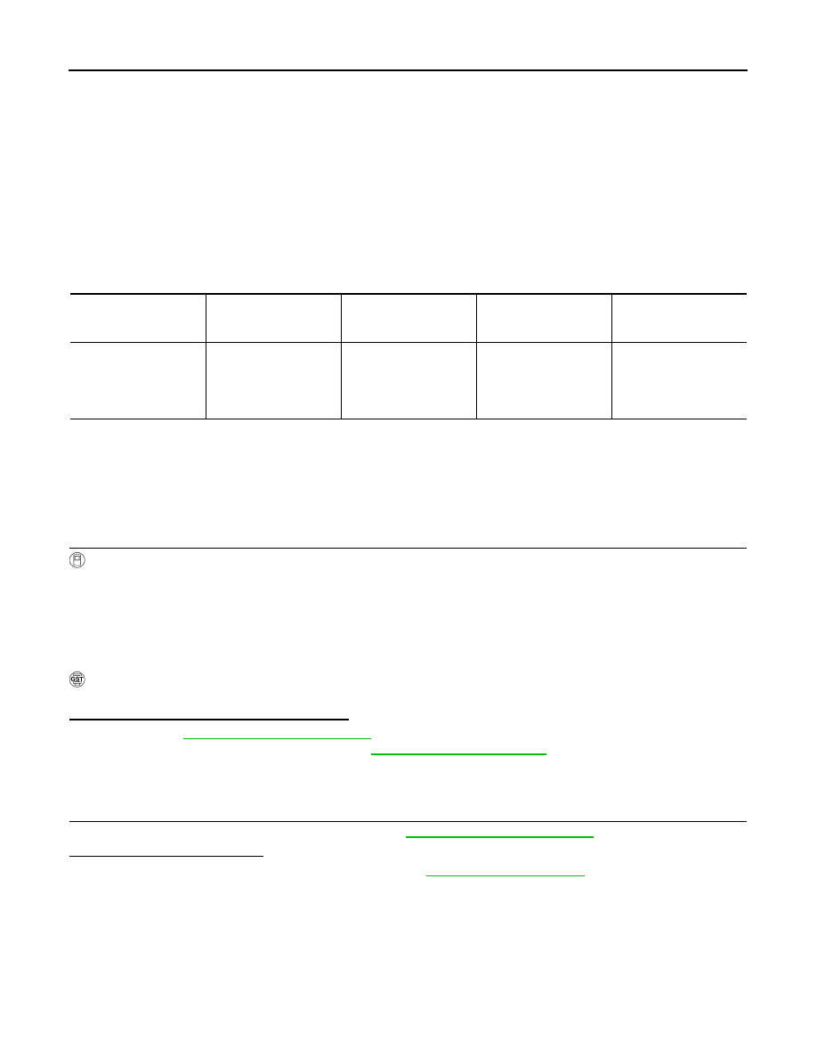
DTC
Item
(CONSULT-III screen
terms)
A/T CHECK indicator
lamp judgment flicker
Diagnostic item is de-
tected when...
Possible cause
P1772
LC/B SOLENOID/CIRC
7th
Normal voltage not ap-
plied to solenoid due to
cut line, short, or the like.
• Harness or connectors
(Solenoid circuit is
open or shorted.)
• Low coast brake sole-
noid valve
GEAR
: “1” or “2” (LC/B ON/OFF)
MANU MODE SW
: ON
P1774 LOW COAST BRAKE SOLENOID VALVE FUNCTION
TM-83
< COMPONENT DIAGNOSIS >
[5AT: RE5R05A]
C
E
F
G
H
I
J
K
L
M
A
B
TM
N
O
P
P1774 LOW COAST BRAKE SOLENOID VALVE FUNCTION
Description
INFOID:0000000003130550
• Low coast brake solenoid valve is turned ON or OFF by the TCM in response to signals transmitted from the
PNP switch, vehicle speed sensor and accelerator pedal position sensor (throttle position sensor). Gears will
then be shifted to the optimum position.
• This is not only caused by electrical malfunction (circuits open or shorted) but also by mechanical malfunc-
tion such as control valve sticking, improper solenoid valve operation.
DTC Logic
INFOID:0000000003130551
DTC DETECTION LOGIC
DTC CONFIRMATION PROCEDURE
CAUTION:
Always drive vehicle at a safe speed.
NOTE:
If “DTC CONFIRMATION PROCEDURE” has been previously performed, always turn ignition switch
OFF. Then wait at least 10 seconds before performing the next test.
1.
CHECK DTC DETECTION
With CONSULT-III
1.
Start the engine.
2.
Select “Data Monitor” mode for “TRANSMISSION”.
3.
Drive vehicle and maintain the following conditions.
4.
Stop vehicle and perform step 3 again.
5.
Stop vehicle.
6.
Turn ignition switch OFF, then perform step 1 to 4 again.
With GST
Follow the procedure “With CONSULT-III”.
Is “P1774 LC/B SOLENOID FNCT” detected?
YES
>> Go to
NO
>> Check intermittent incident. Refer to
GI-38, "Intermittent Incident"
.
Diagnosis Procedure
INFOID:0000000003130552
1.
CHECK TCM POWER SUPPLY AND GROUND CIRCUIT
Check TCM power supply and ground circuit. Refer to
Is the inspection result normal?
YES
>> Replace the control valve with TCM. Refer to
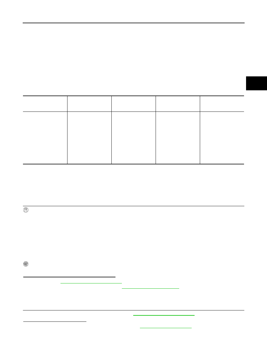
DTC
Item
(CONSULT-III screen
terms)
A/T CHECK indicator
lamp judgment flicker
Diagnostic item is de-
tected when...
Possible cause
P1774
LC/B SOLENOID FNCT
7th
• TCM detects an im-
proper voltage drop
when it tries to operate
the solenoid valve.
• Condition of ATF pres-
sure switch 2 is differ-
ent from monitor
value, and relation be-
tween gear position
and actual gear ratio is
irregular.
• Harness or connectors
(Solenoid and switch
circuit is open or short-
ed.)
• Low coast brake sole-
noid valve
• ATF pressure switch 2
GEAR
: “1” or “2” (LC/B ON/OFF)
MANU MODE SW
: ON
Нет комментариевНе стесняйтесь поделиться с нами вашим ценным мнением.
Текст