Infiniti EX35. Manual — part 1424
TM-84
< COMPONENT DIAGNOSIS >
[5AT: RE5R05A]
P1774 LOW COAST BRAKE SOLENOID VALVE FUNCTION
NO
>> Repair or replace damaged parts.

P1815 MANUAL MODE SWITCH
TM-85
< COMPONENT DIAGNOSIS >
[5AT: RE5R05A]
C
E
F
G
H
I
J
K
L
M
A
B
TM
N
O
P
P1815 MANUAL MODE SWITCH
Description
INFOID:0000000003130553
Manual mode switch is installed in control device assembly. It transmits manual mode switch, shift up and shift
down switch signals to unified meter and A/C amp. Then unified meter and A/C amp. transmits signals to TCM
with CAN communication.
TCM transmits the switch signals to unified meter and A/C amp. by CAN communication line. Then manual
mode switch position is indicated on the A/T indicator. For inspection, refer to
.
DTC Logic
INFOID:0000000003130554
DTC DETECTION LOGIC
DTC CONFIRMATION PROCEDURE
CAUTION:
Always drive vehicle at a safe speed.
NOTE:
If “DTC CONFIRMATION PROCEDURE” has been previously performed, always turn ignition switch
OFF. Then wait at least 10 seconds before performing the next test.
1.
CHECK DTC DETECTION
With CONSULT-III
1.
Start the engine.
2.
Select “Data Monitor” mode for “TRANSMISSION”.
3.
Drive vehicle and maintain the following conditions for at least 2 consecutive seconds.
Is “P1815 MANU MODE SW/CIRC” detected?
YES
>> Go to
NO
>> Check intermittent incident. Refer to
GI-38, "Intermittent Incident"
.
Diagnosis Procedure
INFOID:0000000003130555
1.
CHECK MANUAL MODE SWITCH CIRCUIT
1.
Turn ignition switch OFF.
2.
Disconnect control device connector.
3.
Turn ignition switch ON.
4.
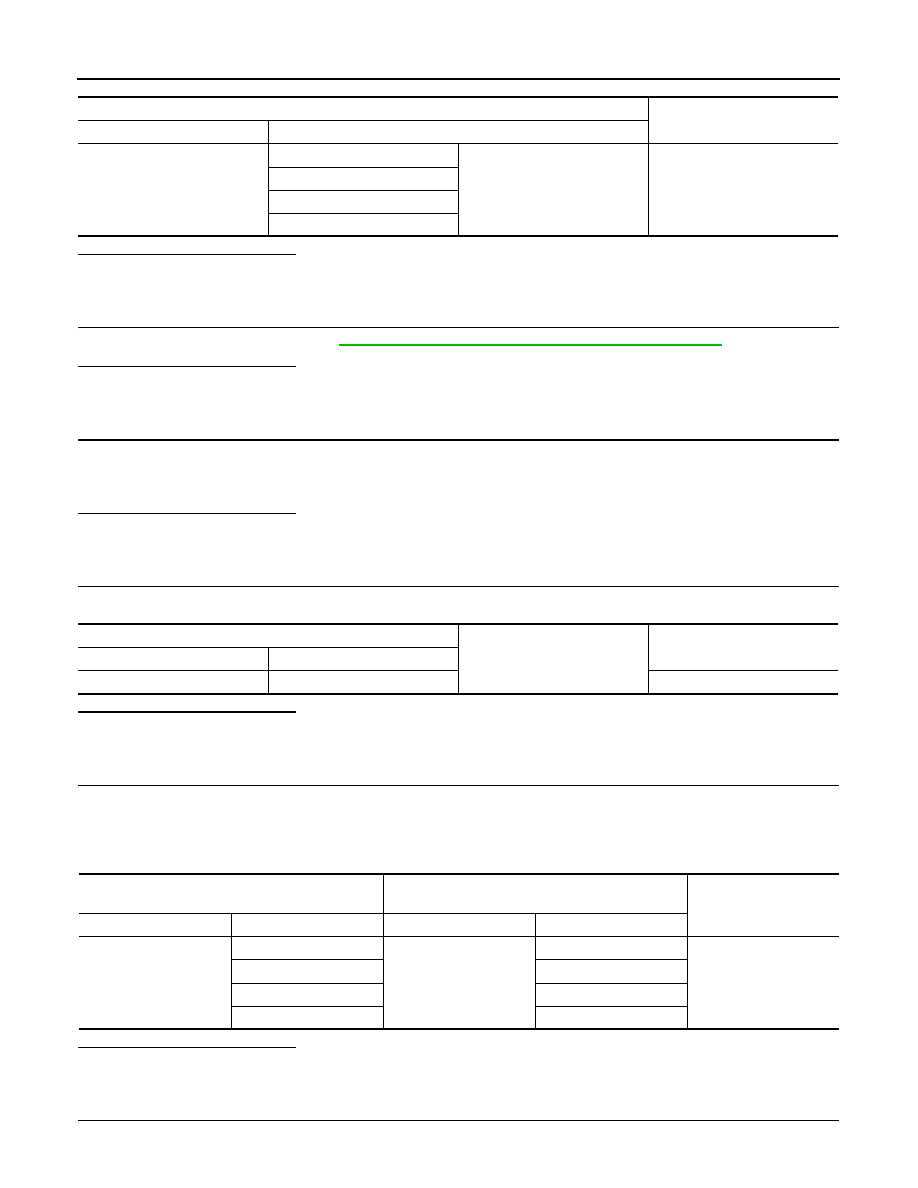
Check voltage between control device vehicle side harness connector terminals.
DTC
Item
(CONSULT-III screen
terms)
A/T CHECK indicator
lamp judgment flicker
Diagnostic item is detect-
ed when...
Possible cause
P1815
MANU MODE SW/CIRC
—
TCM monitors manual
mode, non manual
mode, up or down switch
signal, and detects as ir-
regular when impossible
input pattern occurs 2
second or more.
• Harness or connectors
(These switches circuit
is open or shorted.)
• Manual mode select
switch (Into control de-
vice)
• Manual mode position
select switch (Into con-
trol device)
MANU MODE SW
: ON
TM-86
< COMPONENT DIAGNOSIS >
[5AT: RE5R05A]
P1815 MANUAL MODE SWITCH
Is the inspection result normal?
YES
>> GO TO 2.
NO
>> GO TO 4.
2.
CHECK MANUAL MODE SWITCH
Check manual mode switch. Refer to
TM-87, "Component Inspection (Manual Mode Switch)"
.
Is the inspection result normal?
YES
>> GO TO 3.
NO
>> Repair or replace damaged parts.
3.
CHECK MALFUNCTIONING ITEM
Check the following.
• Check terminals of control device harness connector and harness cladding for damage.
• Check connector for loose connection.
Is the inspection result normal?
YES
>> GO TO 8.
NO
>> Repair or replace damaged parts.
4.
CHECK GROUND CIRCUIT
Check continuity between control device vehicle side harness connector terminal and ground.
Is the inspection result normal?
YES
>> GO TO 5.
NO
>> Repair or replace damaged parts.
5.
CHECK HARNESS BETWEEN CONTROL DEVICE AND UNIFIED METER AND A/C AMP. (STEP 1)
1.
Turn ignition switch OFF.
2.
Disconnect unified meter and A/C amp. connector.
3.
Check continuity between control device vehicle side harness connector terminals and unified meter and
A/C amp. vehicle side harness connector terminals.
Is the inspection result normal?
YES
>> GO TO 6.
NO
>> Repair or replace damaged parts.
6.
CHECK HARNESS BETWEEN CONTROL DEVICE AND UNIFIED METER AND A/C AMP. (STEP 2)
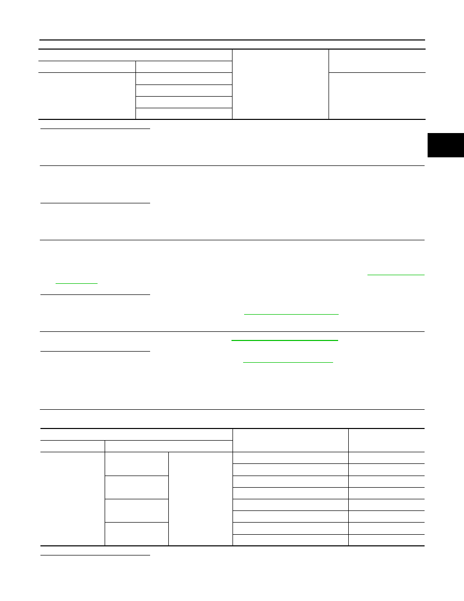
Check continuity between control device vehicle side harness connector terminals and ground.
Control device vehicle side harness connector
Voltage (Approx.)
Connector
Terminal
M137
1
4
Battery voltage
2
3
5
Control device vehicle side harness connector
Ground
Continuity
Connector
Terminal
M137
4
Existed
Control device vehicle side harness connector
Unified meter and A/C amp. vehicle side harness
connector
Continuity
Connector
Terminal
Connector
Terminal
M137
1
M66
10
Existed
2
25
3
5
5
11
P1815 MANUAL MODE SWITCH
TM-87
< COMPONENT DIAGNOSIS >
[5AT: RE5R05A]
C
E
F
G
H
I
J
K
L
M
A
B
TM
N
O
P
Is the inspection result normal?
YES
>> GO TO 7.
NO
>> Repair or replace damaged parts.
7.
CHECK MALFUNCTIONING ITEM
Check the following.
• Check terminals of unified meter and A/C amp. connector for damage.
• Check connector for loose connection.
Is the inspection result normal?
YES
>> GO TO 8.
NO
>> Repair or replace damaged parts.
8.
CHECK UNIFIED METER AND A/C AMP.
1.
Reconnect all the connectors.
2.
Turn ignition switch ON.
3.
Select “M RANGE SW”, “NM RANGE SW”, “AT SFT UP SW” and “AT SFT DWN SW” on “Data Monitor”
mode for “METER/M&A”, and check the On/Off operations of each monitor item. Refer to
Is the inspection result normal?
YES
>> GO TO 9.
NO
>> Replace unified meter and A/C amp. Refer to
9.
CHECK TCM POWER SUPPLY AND GROUND CIRCUIT
Check TCM power supply and ground circuit. Refer to
Is the inspection result normal?
YES
>> Replace the control valve with TCM. Refer to
NO
>> Repair or replace damaged parts.
Component Inspection (Manual Mode Switch)
INFOID:0000000003130556
1.
CHECK MANUAL MODE SWITCH
Check continuity between terminals.
Is the inspection result normal?
YES
>> INSPECTION END
Control device vehicle side harness connector
Ground
Continuity
Connector
Terminal
M137
1
Not existed
2
3
5
Control device harness connector
Condition
Continuity
Connector Terminal
M137
1
4
Selector lever: Manual (Neutral)
Existed
Other than the above
Not existed
2
Selector lever: DOWN (
−
side)
Existed
Other than the above
Not existed
3
Selector lever: UP (+ side)
Existed
Other than the above
Not existed
5
Selector lever: “D” position (Auto)
Existed
Other than the above
Not existed
Нет комментариевНе стесняйтесь поделиться с нами вашим ценным мнением.
Текст