Infiniti EX35. Manual — part 66
AV
U1243 DISPLAY UNIT
AV-45
< COMPONENT DIAGNOSIS >
[BASE AUDIO WITHOUT NAVIGATION]
C
D
E
F
G
H
I
J
K
L
M
B
A
O
P
U1243 DISPLAY UNIT
Description
INFOID:0000000003508385
DTC Logic
INFOID:0000000003508386
Diagnosis Procedure
INFOID:0000000003508387
1.
CHECK DISPLAY UNIT POWER SUPPLY AND GROUND CIRCUIT
Check display unit power supply and ground circuits. Refer to
AV-51, "DISPLAY UNIT : Diagnosis Procedure"
.
Is the inspection result normal?
YES
>> GO TO 2.
NO
>> Repair malfunctioning parts.
2.
CHECK CONTINUITY COMMUNICATION CIRCUIT
1.
Turn ignition switch OFF.
2.
Disconnect display unit connector and AV control unit connector.
3.
Check continuity between display unit harness connector and AV control unit harness connector.
4.
Check continuity between display unit harness connector and ground.
Is the inspection result normal?
YES
>> GO TO 3.
NO
>> Repair harness or connector.
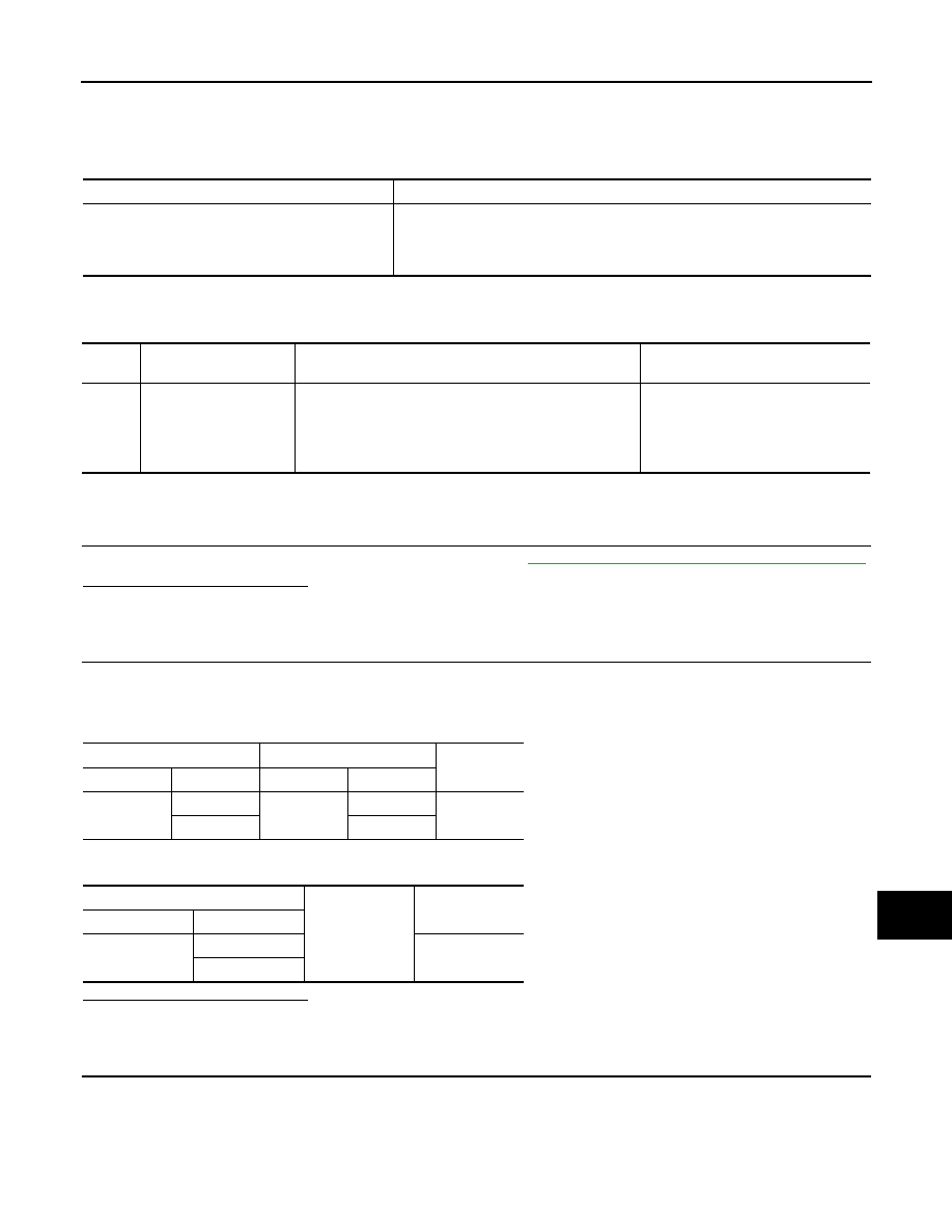
3.
CHECK COMMUNICATION SIGNAL (CONT
→
DISP)
1.
Connect display unit connector and AV control unit connector.
2.
Turn ignition switch ON.
3.
Check signal between display unit harness connector and ground.
Part name
Description
DISPLAY UNIT
• Display image is controlled by the serial communication from AV control unit.
• Inputs the RGB image signal (RGB, RGB area and RGB synchronizing) from
AV control unit and the auxiliary image signal from the auxiliary input jacks.
• Outputs the synchronizing signals (HP and VP) to the AV control unit.
DTC
Display contents of
CONSULT-III
DTC Detection Condition
Possible causes
U1243
FRONT DISP CONN
[U1243]
When either one of the following items is detected:
• Display unit power supply and ground circuits malfunc-
tion is detected.
• Malfunction is detected in communication circuits be-
tween AV control unit and display unit.
• Display unit power supply and
ground circuits.
• Communication circuits between
AV control unit and display unit.
Display unit
AV control unit
Continuity
Connector
Terminals
Connector
Terminals
M71
11
M83
56
Existed
22
44
Display unit
Ground
Continuity
Connector
Terminals
M71
11
Not existed
22
AV-46
< COMPONENT DIAGNOSIS >
[BASE AUDIO WITHOUT NAVIGATION]
U1243 DISPLAY UNIT
Is the inspection result normal?
YES
>> GO TO 4.
NO
>> Replace AV control unit.
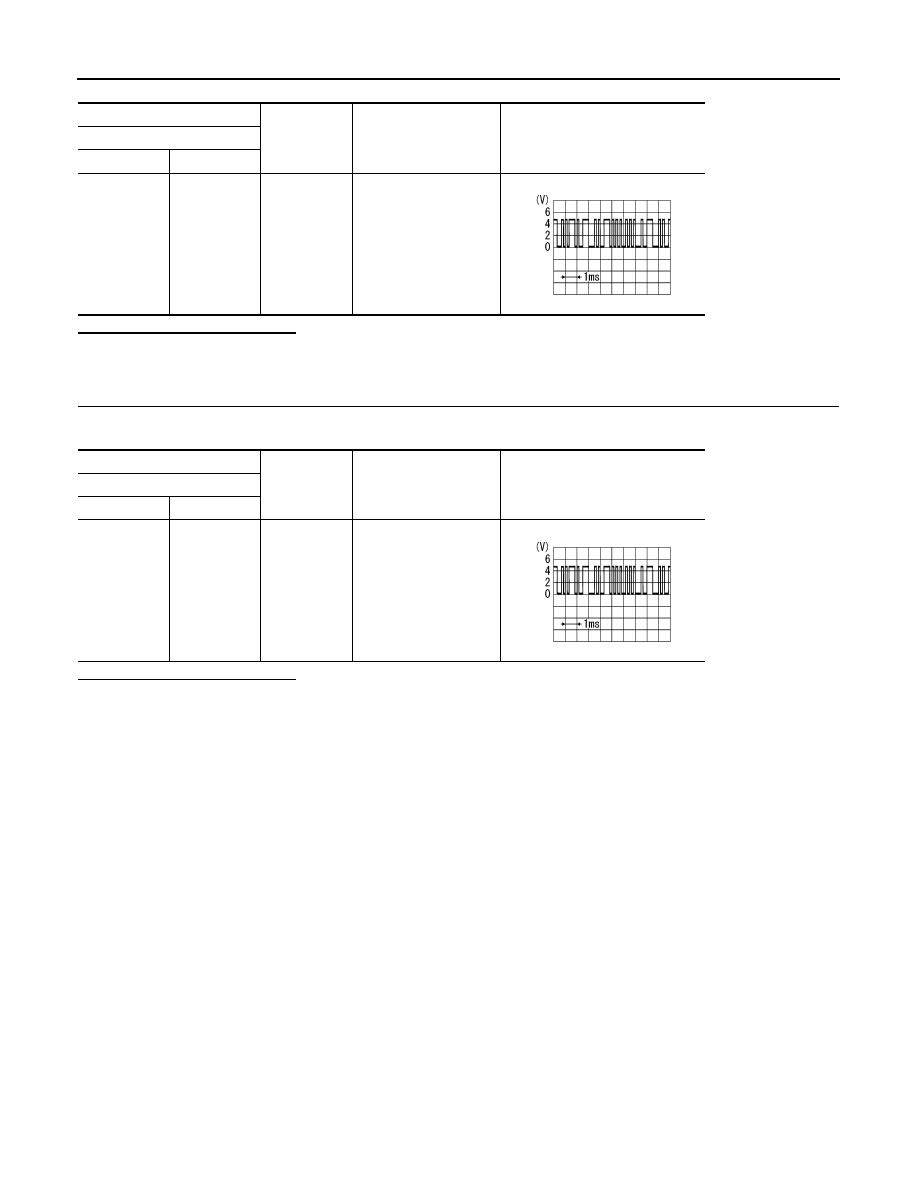
4.
CHECK COMMUNICATION SIGNAL (DISP
→
CONT)
Check signal between display unit harness connector and ground.
Is the inspection result normal?
YES
>> INSPECTION END
NO
>> Replace display unit.
(+)
(
−
)
Condition
Reference value
Display unit
Connector
Terminal
M71
11
Ground
When adjusting display
brightness.
PKIB5039J
(+)
(
−
)
Condition
Reference value
Display unit
Connector
Terminal
M71
22
Ground
When adjusting display
brightness.
PKIB5039J
AV
U1250 CAMERA CONTROL UNIT
AV-47
< COMPONENT DIAGNOSIS >
[BASE AUDIO WITHOUT NAVIGATION]
C
D
E
F
G
H
I
J
K
L
M
B
A
O
P
U1250 CAMERA CONTROL UNIT
Description
INFOID:0000000003529091
DTC Logic
INFOID:0000000003529092
Diagnosis Procedure
INFOID:0000000003529093
1.
CHECK CAMERA-CONNECTION RECOGNITION SIGNAL CIRCUIT
1.
Turn ignition switch OFF.
2.
Disconnect AV control unit connector and camera control unit connector.
3.
Check continuity between AV control unit harness connector and camera control unit harness connector.
Is inspection result normal?
YES
>> GO TO 2.
NO
>> Repair harness or connector.
2.
CHECK AV CONTROL UNIT VOLTAGE
1.
Connect AV control unit connector.
2.
Turn ignition switch ON.
3.
Check voltage between AV control unit harness connector and ground.
Is inspection result normal?
YES
>> Replace camera control unit.
NO
>> Replace AV control unit.
Part name
Description
CAMERA CONTROL UNIT
• Camera image signal is input from rear view camera, and camera image is in-
dicated on the display.
• Power (camera ON signal) is sent to rear view camera.
• Controlled by AV communication sent from AV control unit.
• AV control unit recognizes the presence of camera system with camera con-
nection recognition signal.
DTC
Display contents of
CONSULT-III
DTC Detection Condition
Possible causes
U1250
CAMERA CONT. CONN
[U1250]
A malfunction is detected in Camera-connection recogni-
tion signal circuit
Camera-connection recognition sig-
nal circuit
AV control unit
Camera control unit
Continuity
Connector
Terminal
Connector
Terminal
M84
68
B50
14
Existed
(+)
(
−
)
Voltage
(Approx.)
AV control unit
Connector
Terminal
M84
68
Ground
5.0 V
AV-48
< COMPONENT DIAGNOSIS >
[BASE AUDIO WITHOUT NAVIGATION]
U1255 SATELLITE RADIO TUNER
U1255 SATELLITE RADIO TUNER
Description
INFOID:0000000003508388
DTC Logic
INFOID:0000000003508389
Diagnosis Procedure
INFOID:0000000003508390
1.
CHECK SATELLITE RADIO TUNER POWER SUPPLY AND GROUND CIRCUIT
Check satellite radio tuner power supply and ground circuit. Refer to
AV-54, "SATELLITE RADIO TUNER :
Is the inspection result normal?
YES
>> GO TO 2.
NO
>> Repair malfunctioning parts.
2.
CHECK CONTINUITY COMMUNICATION CIRCUIT AND REQUEST SIGNAL CIRCUIT
1.
Turn ignition switch OFF.
2.
Disconnect AV control unit connector and satellite radio tuner connector.
3.
Check continuity between AV control unit harness connector and satellite radio tuner harness connector.
4.
Check continuity between AV control unit harness connector and ground.
Is the inspection result normal?
YES
>> GO TO 3.
NO
>> Repair harness or connector.
Part name
Description
SATELLITE RADIO TUNER
• Inputs the satellite radio signal from satellite radio antenna and outputs it to the
AV control unit.
• It is controlled with the communication (communication signal, request signal)
from AV control unit.
DTC
Display contents of
CONSULT-III
DTC Detection Condition
Possible causes
U1255
SAT CONN
[U1255]
When either one of the following items is detected:
• Satellite radio tuner power supply and ground circuits
malfunction is detected.
• Malfunction is detected in communication circuits be-
tween AV control unit and satellite radio tuner.
• Malfunction is detected in request signal circuit be-
tween AV control unit and satellite radio tuner.
• Satellite radio tuner power supply
and ground circuits.
• Communication circuits between
AV control unit and satellite radio
tuner.
• Request signal circuit between AV
control unit and satellite radio tun-
er.
AV control unit
Satellite radio tuner
Continuity
Connector
Terminals
Connector
Terminals
M82
28
B236
8
Existed
29
9
30
10
AV control unit
Ground
Continuity
Connector
Terminals
M82
28
Not existed
29
30
Нет комментариевНе стесняйтесь поделиться с нами вашим ценным мнением.
Текст