Infiniti EX35. Manual — part 64
AV
DIAGNOSIS SYSTEM (AV CONTROL UNIT)
AV-37
< FUNCTION DIAGNOSIS >
[BASE AUDIO WITHOUT NAVIGATION]
C
D
E
F
G
H
I
J
K
L
M
B
A
O
P
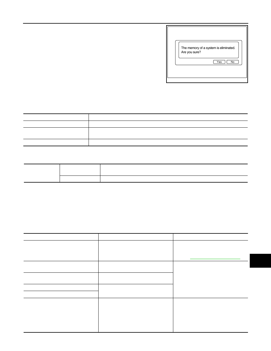
Initializes AV control unit memory.
CONSULT-III Function (MULTI AV)
INFOID:0000000003508372
CONSULT-III FUNCTIONS
CONSULT-III performs the following functions via the communication with AV control unit.
AV COMMUNICATION
When “AV communication” of “CAN Diag Support Monitor” is selected, the following function will be performed.
ECU IDENTIFICATION
The part number of AV control unit is displayed.
SELF DIAGNOSIS RESULT
• In CONSULT-III self-diagnosis, self-diagnosis results and error history are displayed simultaneously.
• The timing is displayed as “0” if any of the error codes [U1000], [U1010], [U1300] or [U1310] are detected.
The counter increases by 1 if the condition is normal at the next ignition switch ON cycle.
Self-diagnosis results display item
JSNIA0155GB
Diagnosis mode
Description
Ecu Identification
The part number of AV control unit can be checked.
Self Diagnostic Result
Performs a diagnosis on the AV control unit, a connection diagnosis for the communication cir-
cuit of the Multi AV system and displays the current and past malfunctions collectively.
Data Monitor
The diagnosis of vehicle signal that is input to AV control unit can be performed.
AV communication
AV&NAVI C/U
Displays the communication status from AV control unit to each unit as well as the error
counter.
AUDIO
Displays AV control unit communication status and the error counter.
Error item
Description
Possible malfunction factor/Action to take
CAN COMM CIRCUIT [U1000]
CAN communication malfunction is detect-
ed.
Perform diagnosis with CONSULT-III, and
then repair the malfunctioning parts accord-
ing to the diagnosis results.
Refer to
.
CONTROL UNIT (CAN) [U1010]
CAN initial diagnosis malfunction is detect-
ed.
Replace AV control unit.
CONTROL UNIT (AV) [U1310]
AV communication circuit initial diagnosis
malfunction is detected.
Control Unit FLASH-ROM [U1200]
AV control unit malfunction is detected.
CAN CONT [U1216]
FRONT DISP CONN [U1243]
When either one of the following items
are detected:
• Display unit power supply or ground cir-
cuits malfunction are detected.
• Malfunction is detected in the communi-
cation circuits between AV control unit
and display unit.
• Display unit power supply and ground
circuit.
• Communication circuit between AV con-
trol unit and display unit.
AV-38
< FUNCTION DIAGNOSIS >
[BASE AUDIO WITHOUT NAVIGATION]
DIAGNOSIS SYSTEM (AV CONTROL UNIT)
DATA MONITOR
ALL SIGNALS
• Displays the status of the following vehicle signals inputted into the AV control unit.
• For each signal, actual signal can be compared with the condition recognized on the system.
SELECTION FROM MENU
Allows the technician to select which vehicle signals should be displayed and displays the status of the
selected vehicle signals.
CAMERA CONT. CONN [U1250]
Malfunction is detected in the camera con-
nection recognition circuit between AV con-
trol unit and camera control unit.
Camera-connection recognition circuit be-
tween AV control unit and camera control
unit.
SAT CONN [U1255]
When either one of the following items
are detected:
• Satellite radio tuner power supply or
ground circuits malfunction are detected.
• Malfunction is detected in the communi-
cation circuits between AV control unit
and satellite radio tuner.
• Malfunction is detected in the request
signal circuits between AV control unit
and satellite radio tuner.
• Satellite radio tuner power supply and
ground circuits.
• Communication circuits between AV con-
trol unit and satellite radio tuner.
• Request signal circuit between AV con-
trol unit and satellite radio tuner.
• AV COMM CIRCUIT [U1300]
• SWITCH CONN [U1240]
When either one of the following items
are detected:
• Multifunction switch power supply or
ground circuits malfunction are detected.
• Malfunction is detected in the AV com-
munication circuits between AV control
unit and multifunction switch.
• Multifunction switch power supply and
ground circuits.
• AV communication circuits between AV
control unit and multifunction switch.
• AV COMM CIRCUIT [U1300]
• REAR CAMERA LAN CONN [U1252]
When either one of the following items
are detected:
• Camera control unit power supply or
ground circuits malfunction are detected.
• Malfunction is detected in the AV com-
munication circuits between camera con-
trol unit and the junction between AV
control unit and multifunction switch.
• Camera control unit power supply and
ground circuits.
• AV communication circuits between cam-
era control unit and the junction between
AV control unit and multifunction switch.
• AV COMM CIRCUIT [U1300]
• SWITCH CONN [U1240]
• REAR CAMERA LAN CONN [U1252]
Malfunction is detected in the AV communi-
cation circuits between AV control unit and
the junction between camera control unit
and multifunction switch.
AV communication circuits between AV
control unit and the junction between cam-
era control unit and multifunction switch.
Error item
Description
Possible malfunction factor/Action to take
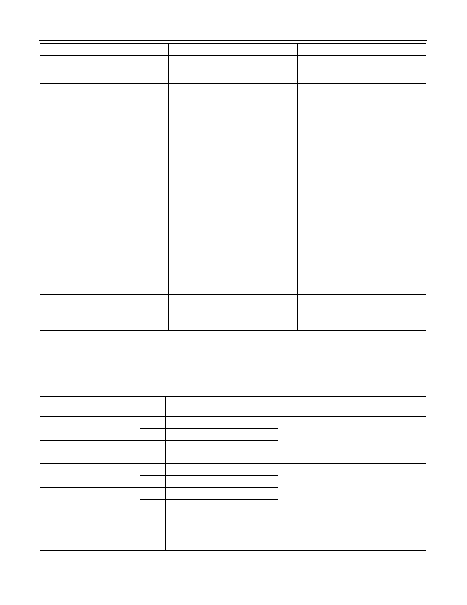
Display Item
Dis-
play
Vehicle status
Remarks
VHCL SPD SIG
On
Vehicle speed > 0 km/h (0 MPH)
Changes in indication may be delayed. This is nor-
mal.
Off
Vehicle speed = 0 km/h (0 MPH)
PKB SIG
On
Parking brake is applied.
Off
Parking brake is released.
ILLUM SIG
On
Light switch ON
—
Off
Light switch OFF
IGN SIG
On
Ignition switch ON
Off
Ignition switch in the ACC position
REV SIG
On
Shift the selector lever to the “R” posi-
tion
Changes in indication may be delayed. This is nor-
mal.
Off
Shift the selector lever to a position
other than the “R” position

AV
DIAGNOSIS SYSTEM (AV CONTROL UNIT)
AV-39
< FUNCTION DIAGNOSIS >
[BASE AUDIO WITHOUT NAVIGATION]
C
D
E
F
G
H
I
J
K
L
M
B
A
O
P
Item to be selected
Description
VHCL SPD SIG
The same as when “ALL SIGNALS”
is selected.
PKB SIG
ILLUM SIG
IGN SIG
REV SIG

AV-40
< COMPONENT DIAGNOSIS >
[BASE AUDIO WITHOUT NAVIGATION]
U1000 CAN COMM CIRCUIT
COMPONENT DIAGNOSIS
U1000 CAN COMM CIRCUIT
Description
INFOID:0000000003508373
CAN (Controller Area Network) is a serial communication line for real-time application. It is an on-vehicle mul-
tiplex communication line with high data communication speed and excellent error detection ability. Many elec-
tronic control units are equipped onto a vehicle, and each control unit shares information and links with other
control units during operation (not independently). In CAN communication, control units are connected with 2
communication lines (CAN-H, CAN-L) allowing a high rate of information transmission with less wiring. Each
control unit transmits/receives data but selectively reads required data only.
CAN Communication Signal Chart. Refer to
LAN-27, "CAN System Specification Chart"
DTC Logic
INFOID:0000000003508374
DTC DETECTION LOGIC
Diagnosis Procedure
INFOID:0000000003508375
1.
PERFORM SELF-DIAGNOSTIC
1.
Turn ignition switch ON and wait for 2 seconds or more.
2.
Check “Self Diagnostic Result” of “MULTI AV”.
Is “CAN COMM CIRCUIT” displayed?
YES
>> Refer to “LAN system”. Refer to
LAN-18, "Trouble Diagnosis Flow Chart"
NO
>> Refer to GI section. Refer to
GI-38, "Intermittent Incident"
.
DTC
Display contents of CON-
SULT-III
Diagnostic item is detected when ...
Probable malfunction location
U1000
CAN COMM CIRCUIT
AV control unit is not transmitting or receiving
CAN communication signal for 2 seconds or
more.
CAN communication system.
Нет комментариевНе стесняйтесь поделиться с нами вашим ценным мнением.
Текст