Infiniti EX35. Manual — part 62
AV
DIAGNOSIS SYSTEM (AV CONTROL UNIT)
AV-29
< FUNCTION DIAGNOSIS >
[BASE AUDIO WITHOUT NAVIGATION]
C
D
E
F
G
H
I
J
K
L
M
B
A
O
P
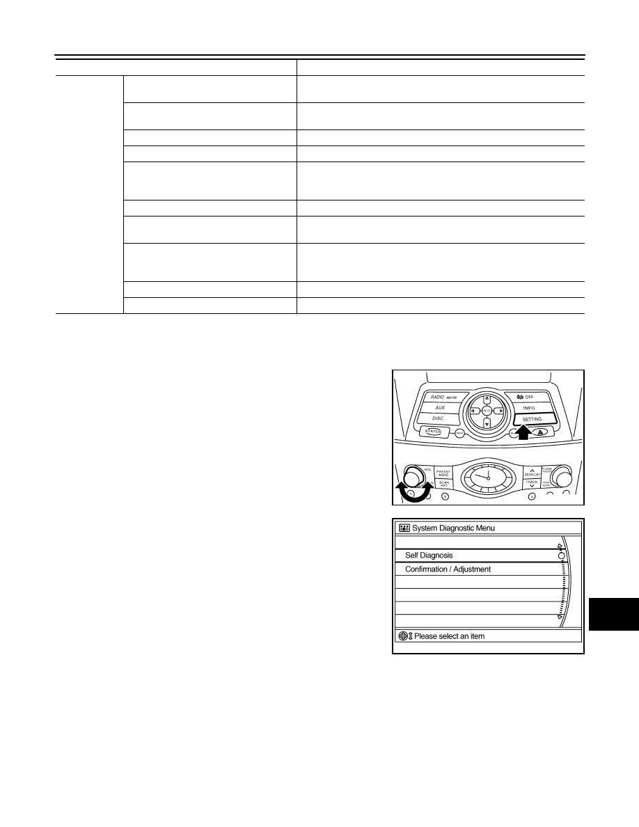
STARTING PROCEDURE
1.
Start the engine.
2.
Turn the audio system OFF.
3.
While pressing the “SETTING” button, turn the volume control
dial clockwise or counterclockwise for 40 clicks or more. (When
the self-diagnosis mode starts, a short beep will sound.)
• Shifting from the current screen to the previous screen is per-
formed by pressing the “BACK” button.
4.
The trouble diagnosis initial screen is displayed, and then the
items of “Self Diagnosis” and “Confirmation/Adjustment” can be
selected.
SELF-DIAGNOSIS MODE
Confirmation/
Adjustment
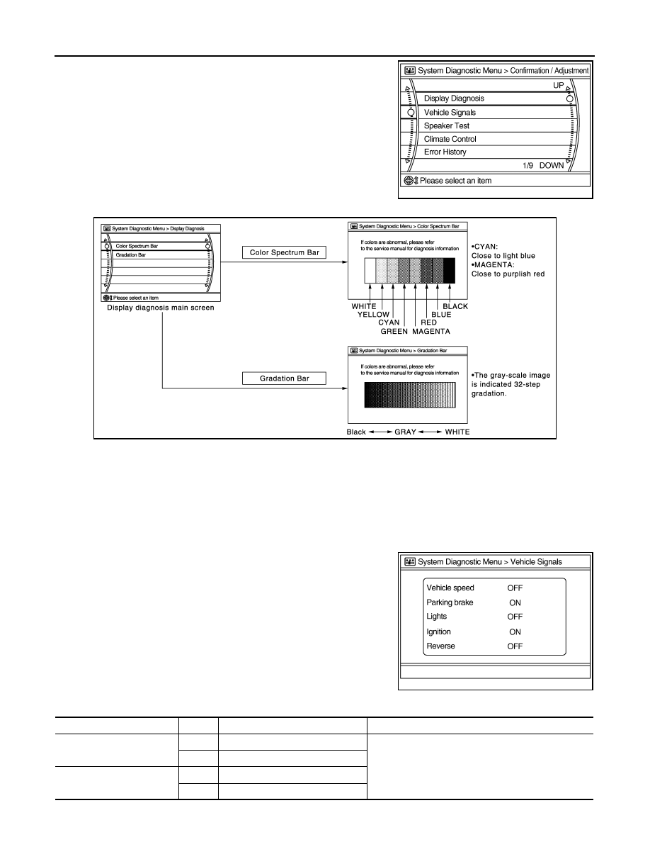
Display Diagnosis
The confirmations of the tint with the color spectrum bar display and
shading of color with the gradation bar display can be performed.
Vehicle Signals
Diagnosis of signals can be performed for vehicle speed, parking brake,
lights, ignition switch, and reverse.
Speaker Test
The connection of a speaker can be confirmed by test tone.
Climate Control
Start auto air conditioner system self-diagnosis.
Error History
The system malfunction and the frequency when occurring in the past
are displayed. When the malfunctioning item is selected, the time and
place that the selected malfunction last occurred are displayed.
Vehicle CAN Diagnosis
The transmitting/receiving of CAN communication can be monitored.
AV COMM Diagnosis
The communication condition of each unit of Multi AV system can be
monitored.
Camera Cont.
The signal connected to camera control unit can be checked and the
guiding line position that overlaps rear view camera image can be adjust-
ed.
Delete Unit Connection Log
Erase the connection history of unit and error history
Initialize Settings
Initializes AV control unit memory.
Mode
Description
JSNIA0137GB
JSNIA0138GB
A
V
- 3
0
< FUNCTION DIAGNOSIS >
[BASE AUDIO WITHOUT NAVIGATION]
DIAGNOSIS SYSTEM (AV CONTROL UNIT)
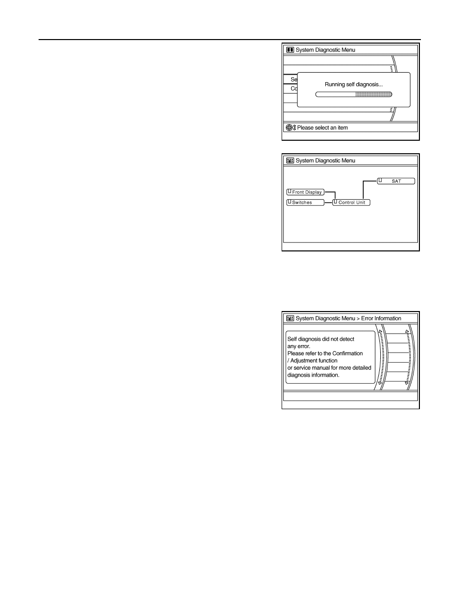
1.
Start the self-diagnosis function and select “Self-diagnosis”.
-
Self-diagnosis subdivision screen is displayed, and the self-
diagnosis mode starts.
-
The bar graph visible on the center of the self-diagnosis subdivi-
sion screen indicates the progress of the trouble diagnosis.
2.
Diagnosis results are displayed after the self-diagnosis is com-
pleted. The unit names and the connection lines are color-coded
according to the diagnostic results.
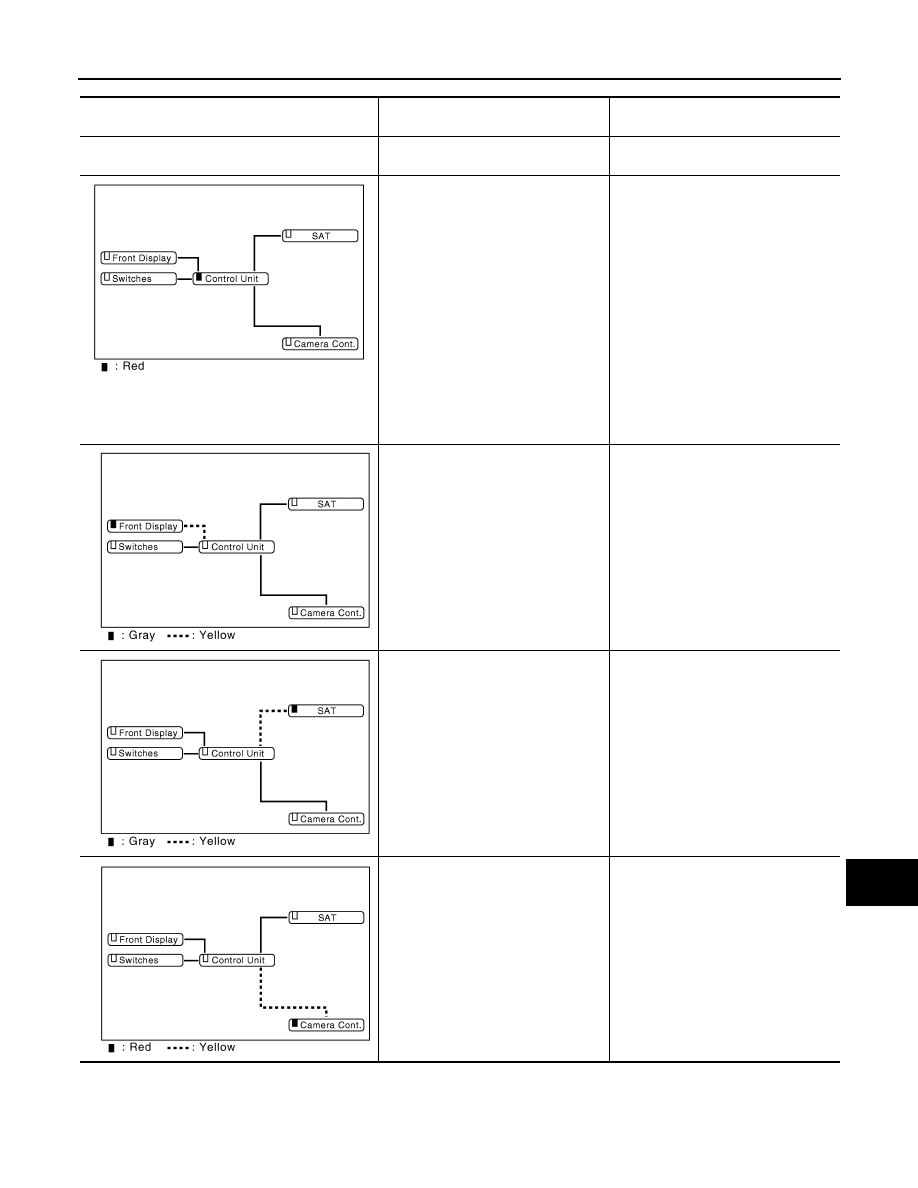
NOTE:
• Only the control unit (AV control unit) is displayed in red.
• Replace AV control unit if “Self-Diagnosis did not run because of a control unit malfunction” is indicated. The symptom is an AV
control unit internal error.
-
If multiple errors occur at the same time for a single unit, the screen switch colors are determined accord-
ing to the following order of priority: red > gray.
-
The comments of the self-diagnosis results can be viewed with a
component in the diagnosis result screen.
SELF-DIAGNOSIS RESULTS
• The self-diagnosis mode allows the technician to diagnose the connection in the communication line
between the AV control unit and each unit, and the internal operation of AV control unit.
• Because the start condition of the diagnosis function is a switch operation, the on board diagnosis function
cannot be started up if any malfunction is detected in the communication circuit between AV control unit and
multifunction switch.
• Check the applicable display in the following table, and then repair the malfunctioning parts.
Self-diagnosis result chart
JSNIA0139GB
Diagnosis results
Unit
Con-
nection
line
Normal
Green
Green
Connection malfunction
Gray
Yellow
Unit malfunction
Note
Red
Green
JSNIA0209GB
JSNIA0141GB
AV
DIAGNOSIS SYSTEM (AV CONTROL UNIT)
AV-31
< FUNCTION DIAGNOSIS >
[BASE AUDIO WITHOUT NAVIGATION]
C
D
E
F
G
H
I
J
K
L
M
B
A
O
P
CONFIRMATION/ADJUSTMENT MODE
1.
Start the diagnosis function and select “Confirmation/Adjustment”. The confirmation/adjustment mode
indicates where each item can be checked or adjusted.
Diagnosis results
Description
Possible malfunction location / Action
to take
“Self-Diagnosis did not run because of a control unit
malfunction”
AV control unit malfunction is detected.
Replace AV control unit.
NOTE:
When a control unit malfunction is detected (red in
the unit display), connection malfunctions with oth-
er connection units may be displayed.
Malfunction is detected in AV control
unit power supply or ground circuits.
Check AV control unit power supply
and ground circuits. When detecting no
malfunction in those components, re-
place AV control unit.
Malfunction is detected in the commu-
nication circuits between AV control
unit and display unit.
Communication circuits between AV
control unit and display unit.
When either one of the following
items are detected:
• Satellite radio tuner power supply or
ground circuits malfunction are de-
tected.
• Malfunction is detected in the com-
munication circuits between AV con-
trol unit and satellite radio tuner.
• Malfunction is detected in the re-
quest signal circuit between AV con-
trol unit and satellite radio tuner.
• Satellite radio tuner power supply
and ground circuits.
• Communication circuits between AV
control unit and satellite radio tuner.
• Request signal circuit between AV
control unit and satellite radio tuner.
A malfunction is detected in the camera
connection recognition circuit between
AV control unit and camera control unit.
Camera connection recognition circuit
between AV control unit and camera
control unit.
JPNIA0829GB
JPNIA0831GB
JPNIA0830GB
JPNIA0832GB
A
V
- 3
2
< FUNCTION DIAGNOSIS >
[BASE AUDIO WITHOUT NAVIGATION]
DIAGNOSIS SYSTEM (AV CONTROL UNIT)
2.
Select each switch on the “Inspection & Adjustment Mode”
screen to display the relevant trouble diagnosis screen. Press
the “RETURN” switch to return to the initial Inspection & Adjust-
ment Mode screen.
Display Diagnosis
The tint of the color bar indication is as per the following list if a RGB signal error is detected.
Vehicle Signals
A comparison check can be made of each actual vehicle signal and
the signals recognized by the system.
JSNIA0147GB
JSNIA0688GB
R (red) signal error
: Light blue (Cyan) tint
G (green) signal error
: Purple (Magenta) tint
B (blue) signal error
: Yellow tint
JSNIA0149GB
Diagnosis item
Display
Vehicle status
Remarks
Vehicle speed
ON
Vehicle speed > 0 km/h (0 MPH)
Changes in indication may be delayed. This is normal.
OFF
Vehicle speed = 0 km/h (0 MPH)
Parking brake
ON
Parking brake is applied.
OFF
Parking brake is released.
Нет комментариевНе стесняйтесь поделиться с нами вашим ценным мнением.
Текст