Infiniti EX35. Manual — part 630
EC-262
< COMPONENT DIAGNOSIS >
[VQ35HR]
P0420, P0430 THREE WAY CATALYST FUNCTION
P0420, P0430 THREE WAY CATALYST FUNCTION
DTC Logic
INFOID:0000000003133419
DTC DETECTION LOGIC
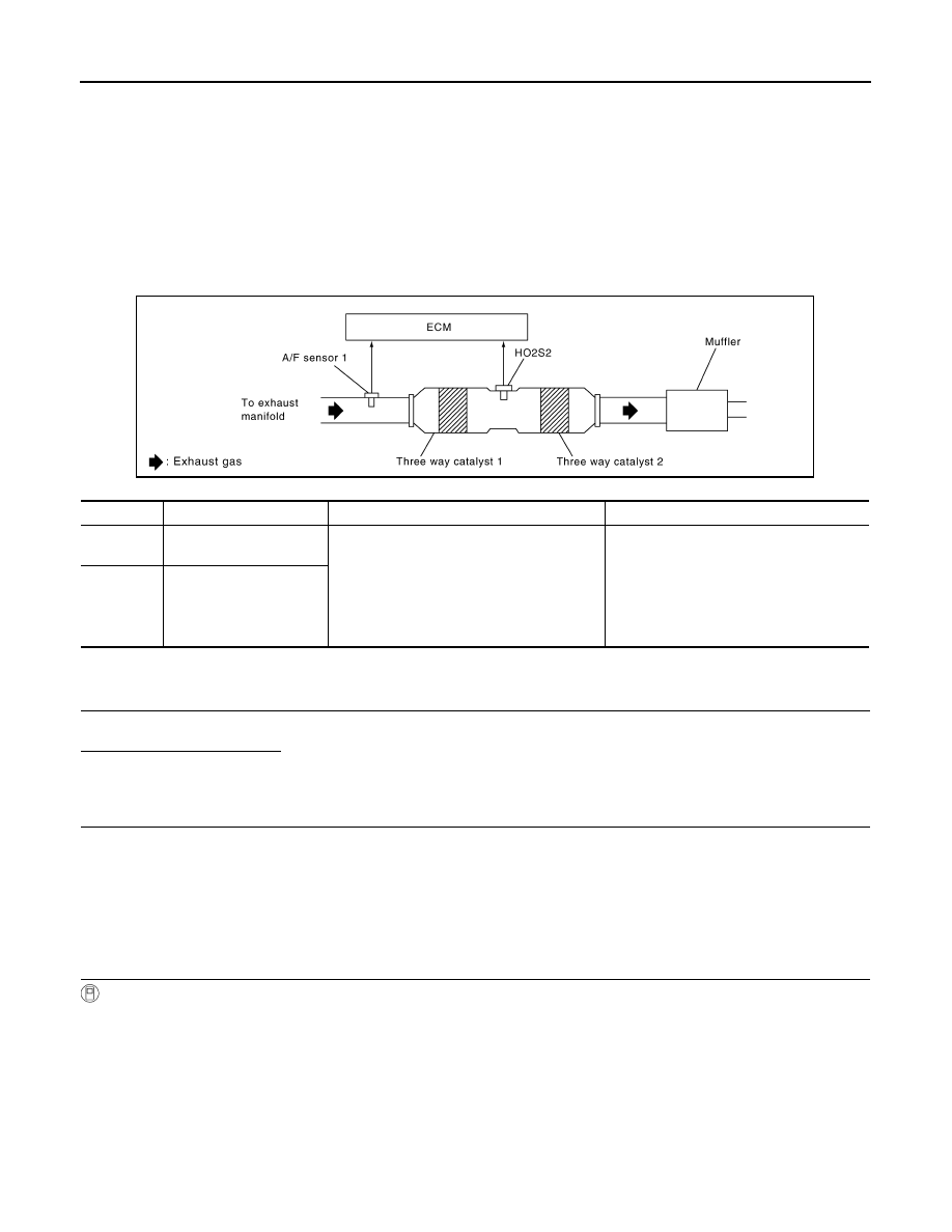
The ECM monitors the switching frequency ratio of air fuel ratio (A/F) sensor 1 and heated oxygen sensor 2.
A three way catalyst 1 with high oxygen storage capacity will indicate a low switching frequency of heated oxy-
gen sensor 2. As oxygen storage capacity decreases, the heated oxygen sensor 2 switching frequency will
increase.
When the frequency ratio of A/F sensor 1 and heated oxygen sensor 2 approaches a specified limit value, the
three way catalyst 1 malfunction is diagnosed.
DTC CONFIRMATION PROCEDURE
1.
INSPECTION START
Do you have CONSULT-III?
Do you have CONSULT-III?
YES
>> GO TO 2.
NO
>> GO TO 7.
2.
PRECONDITIONING
If DTC Confirmation Procedure has been previously conducted, always turn ignition switch OFF and wait at
least 10 seconds before conducting the next test.
TESTING CONDITION:
Do not hold engine speed for more than the specified minutes below.
>> GO TO 3.
3.
PERFORM DTC CONFIRMATION PROCEDURE-I
With CONSULT-III
1.
Turn ignition switch ON and select “DATA MONITOR” mode with CONSULT-III.
2.
Start engine and warm it up to the normal operating temperature.
3.
Turn ignition switch OFF and wait at least 10 seconds.
4.
Start engine and keep the engine speed between 3,500 and 4,000 rpm for at least 1 minute under no load.
5.
Let engine idle for 1 minute.
6.
Check that “COOLAN TEMP/S” indicates more than 70
°
C (158
°
F).
If not, warm up engine and go to next step when “COOLAN TEMP/S” indication reaches to 70
°
C (158
°
F).
7.
Open engine hood.
8.
Select “DTC & SRT CONFIRMATION” then “SRT WORK SUPPORT” mode with CONSULT-III.
DTC No.
Trouble diagnosis name
DTC detecting condition
Possible cause
P0420
Catalyst system efficiency
below threshold (bank 1)
• Three way catalyst (manifold) does not op-
erate properly.
• Three way catalyst (manifold) does not
have enough oxygen storage capacity.
• Three way catalyst (manifold)
• Exhaust tube
• Intake air leaks
• Fuel injector
• Fuel injector leaks
• Spark plug
• Improper ignition timing
P0430
Catalyst system efficiency
below threshold (bank 2)
PBIB1923E

P0420, P0430 THREE WAY CATALYST FUNCTION
EC-263
< COMPONENT DIAGNOSIS >
[VQ35HR]
C
D
E
F
G
H
I
J
K
L
M
A
EC
N
P
O
9.
Rev engine up to 2,000 to 3,000 rpm and hold it for 3 consecutive minutes then release the accelerator
pedal completely.
10. Check the indication of “CATALYST”.
Which is displayed on CONSULT-III screen?
CMPLT >> GO TO 6.
INCMP >> GO TO 4.
4.
PERFORM DTC CONFIRMATION PROCEDURE-II
1.
Wait 5 seconds at idle.
2.
Rev engine up to 2,000 to 3,000 rpm and maintain it until “INCMP” of “CATALYST” changes to “CMPLT” (It
will take approximately 5 minutes).
Does the indication change to “CMPLT”?
YES
>> GO TO 6.
NO
>> GO TO 5.
5.
PERFORM DTC CONFIRMATION PROCEDURE AGAIN
1.
Stop engine and cool it down to less than 70
°
C (158
°
F).
2.
Perform DTC CONFIRMATION PROCEDURE again.
>> GO TO 3.
6.
PERFORM DTC CONFIRMATION PROCEDURE-III
Check 1st trip DTC.
Is 1st trip DTC detected?
YES
>> Go to
NO
>> INSPECTION END
7.
PERFORM COMPONENT FUNCTION CHECK
Perform component function check. Refer to
EC-263, "Component Function Check"
.
NOTE:
Use component function check to check the overall function of the three way catalyst (manifold). During this
check, a 1st trip DTC might not be confirmed.
Is the inspection result normal?
YES
>> INSPECTION END
NO
>> Go to
Component Function Check
INFOID:0000000003133420
1.
PERFORM COMPONENT FUNCTION CHECK
Without CONSULT-III
1.
Start engine and warm it up to the normal operating temperature.
2.
Turn ignition switch OFF and wait at least 10 seconds.
3.
Start engine and keep the engine speed between 3,500 and 4,000 rpm for at least 1 minute under no load.
4.
Let engine idle for 1 minute.
5.
Open engine hood.
6.
Check the voltage between ECM harness connector terminals under the following condition.
DTC
ECM
Condition
Voltage
Connector
+
–
Terminal
Terminal
P0420
F102
76
[HO2S2
(bank 1)]
84
Keeping engine speed at 2,500 rpm
constant under no load
The voltage fluctuation cycle takes more
than 5 seconds.
• 1 cycle: 0.6 - 1.0
→
0 - 0.3
→
0.6 - 1.0
P0430
80
[HO2S2
(bank 2)]
EC-264
< COMPONENT DIAGNOSIS >
[VQ35HR]
P0420, P0430 THREE WAY CATALYST FUNCTION
Is the inspection result normal?
YES
>> INSPECTION END
NO
>> Go to
Diagnosis Procedure
INFOID:0000000003133421
1.
CHECK EXHAUST SYSTEM
Visually check exhaust tubes and muffler for dent.
Is the inspection result normal?
YES
>> GO TO 2.
NO
>> Repair or replace malfunctioning part.
2.
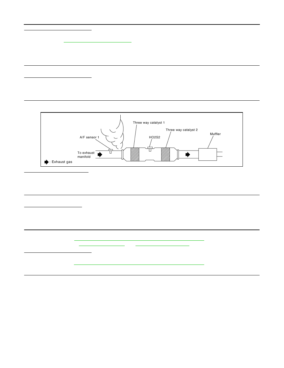
CHECK EXHAUST GAS LEAK
1.
Start engine and run it at idle.
2.
Listen for an exhaust gas leak before the three way catalyst 1.
Is exhaust gas leak detected?
YES
>> Repair or replace malfunctioning part.
NO
>> GO TO 3.
3.
CHECK INTAKE AIR LEAK
Listen for an intake air leak after the mass air flow sensor.
Is intake air leak detected?
YES
>> Repair or replace malfunctioning part.
NO
>> GO TO 4.
4.
CHECK IDLE SPEED AND IGNITION TIMING
Check idle speed and ignition timing.
For procedure, refer to
EC-12, "BASIC INSPECTION : Special Repair Requirement"
For specification, refer to
.
Is the inspection result normal?
YES
>> GO TO 5.
NO
>> Follow the
EC-12, "BASIC INSPECTION : Special Repair Requirement"
5.
CHECK FUEL INJECTORS
1.
Stop engine and then turn ignition switch ON.
2.
Check the voltage between ECM harness connector terminals as follows.
PBIB1922E
P0420, P0430 THREE WAY CATALYST FUNCTION
EC-265
< COMPONENT DIAGNOSIS >
[VQ35HR]
C
D
E
F
G
H
I
J
K
L
M
A
EC
N
P
O
Is the inspection result normal?
YES
>> GO TO 6.
NO
>> Perform
.
6.
CHECK FUNCTION OF IGNITION COIL-I
CAUTION:
Do the following procedure in the place where ventilation is good without the combustible.
1.
Turn ignition switch OFF.
2.
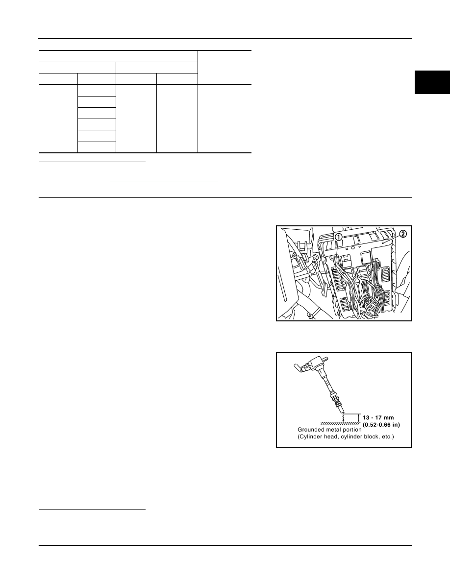
Remove fuel pump fuse (1) in IPDM E/R (2) to release fuel pres-
sure.
NOTE:
Do not use CONSULT-III to release fuel pressure, or fuel pres-
sure applies again during the following procedure.
3.
Start engine.
4.
After engine stalls, crank it two or three times to release all fuel
pressure.
5.
Turn ignition switch OFF.
6.
Remove all ignition coil harness connectors to avoid the electri-
cal discharge from the ignition coils.
7.
Remove ignition coil and spark plug of the cylinder to be
checked.
8.
Crank engine for 5 seconds or more to remove combustion gas in the cylinder.
9.
Connect spark plug and harness connector to ignition coil.
10. Fix ignition coil using a rope etc. with gap of 13 - 17 mm (0.52 -
0.66 in) between the edge of the spark plug and grounded metal
portion as shown in the figure.
11. Crank engine for about 3 seconds, and check whether spark is
generated between the spark plug and the grounded metal por-
tion.
CAUTION:
• Do not approach to the spark plug and the ignition coil
within 50 cm (19.7 in). Be careful not to get an electrical
shock while checking, because the electrical discharge
voltage becomes 20 kV or more.
• It might cause to damage the ignition coil if the gap of more than 17 mm (0.66 in) is taken.
NOTE:
When the gap is less than 13 mm (0.52 in), the spark might be generated even if the coil is mal-
functioning.
Is the inspection result normal?
YES
>> GO TO 10.
NO
>> GO TO 7.
7.
CHECK FUNCTION OF IGNITION COIL-II
1.
Turn ignition switch OFF.
ECM
Voltage
+
–
Connector
Terminal
Connector
Terminal
F102
81
M107
128
Battery voltage
82
85
86
89
90
Spark should be generated.
JMBIA0021ZZ
JMBIA0066GB
Нет комментариевНе стесняйтесь поделиться с нами вашим ценным мнением.
Текст