Infiniti EX35. Manual — part 907
HAC-24
< FUNCTION DIAGNOSIS >
[AUTOMATIC AIR CONDITIONER]
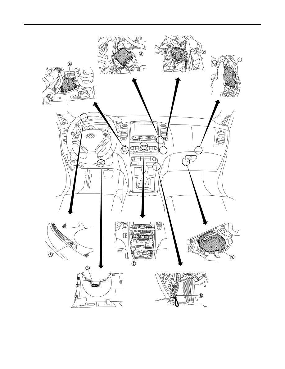
COMPRESSOR CONTROL FUNCTION
WITH LEFT AND RIGHT VENTILATION TEMPERATURE SEPARATELY CONTROL
1.
Intake door motor
2.
Air mix door motor (passenger side)
3.
Mode door motor
4.
Air mix door motor (driver side)
5.
Sunload sensor
6.
In-vehicle sensor
7.
Unified meter and A/C amp.
8.
Intake sensor
9.
Blower motor
JPIIA0716ZZ
COMPRESSOR CONTROL FUNCTION
HAC-25
< FUNCTION DIAGNOSIS >
[AUTOMATIC AIR CONDITIONER]
C
D
E
F
G
H
J
K
L
M
A
B
HAC
N
O
P
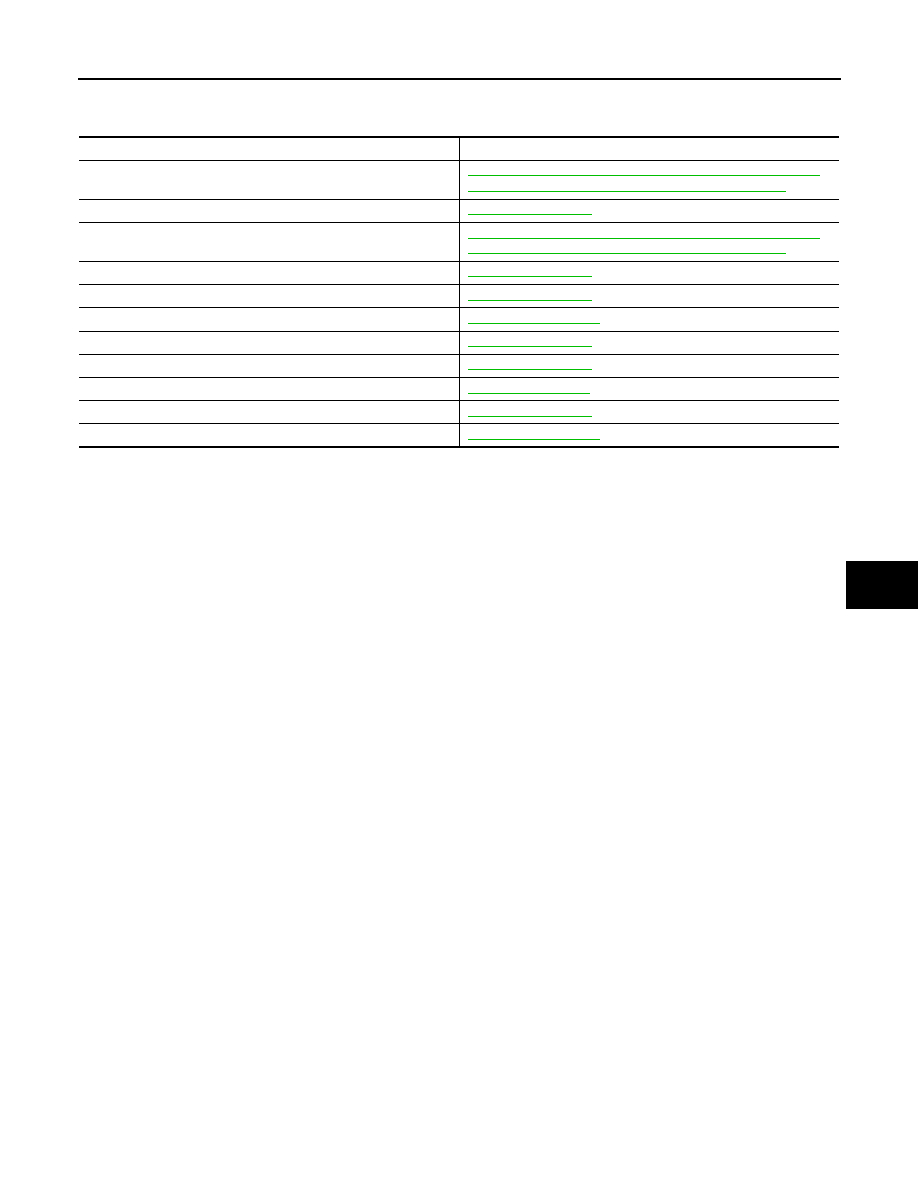
SYSTEM : Component’s role
INFOID:0000000003545575
Component
Reference
Air mix door motor
HAC-74, "WITH LEFT AND RIGHT VENTILATION TEMPERA-
TURE SEPARATELY CONTROL SYSTEM : Description"
Ambient sensor
Blower motor
HAC-83, "WITH LEFT AND RIGHT VENTILATION TEMPERA-
TURE SEPARATELY CONTROL SYSTEM : Description"
Compressor
intake door motor
intake sensor
In-vehicle sensor
Mode door motor
Refrigerant pressure sensor
Sunload sensor
Unified meter and A/C amp.
HAC-26
< FUNCTION DIAGNOSIS >
[AUTOMATIC AIR CONDITIONER]
AUTOMATIC AIR CONDITIONER SYSTEM
AUTOMATIC AIR CONDITIONER SYSTEM
WITHOUT LEFT AND RIGHT VENTILATION TEMPERATURE SEPARATELY
CONTROL SYSTEM
WITHOUT LEFT AND RIGHT VENTILATION TEMPERATURE SEPARATELY CON-
TROL SYSTEM : System Diagram
INFOID:0000000003545576
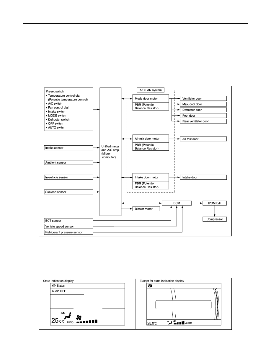
CONTROL SYSTEM
The control system consists of input sensors, switches, unified meter and A/C amp. (microcomputer) and out-
puts. The relationship of these components is as shown in the figure below:
WITHOUT LEFT AND RIGHT VENTILATION TEMPERATURE SEPARATELY CON-
TROL SYSTEM : System Description
INFOID:0000000003545577
CONTROL OPERATION
Display Screen
The operation status of the system is displayed on the screen.
JSIIA1067GB
JSIIA1047GB
AUTOMATIC AIR CONDITIONER SYSTEM
HAC-27
< FUNCTION DIAGNOSIS >
[AUTOMATIC AIR CONDITIONER]
C
D
E
F
G
H
J
K
L
M
A
B
HAC
N
O
P
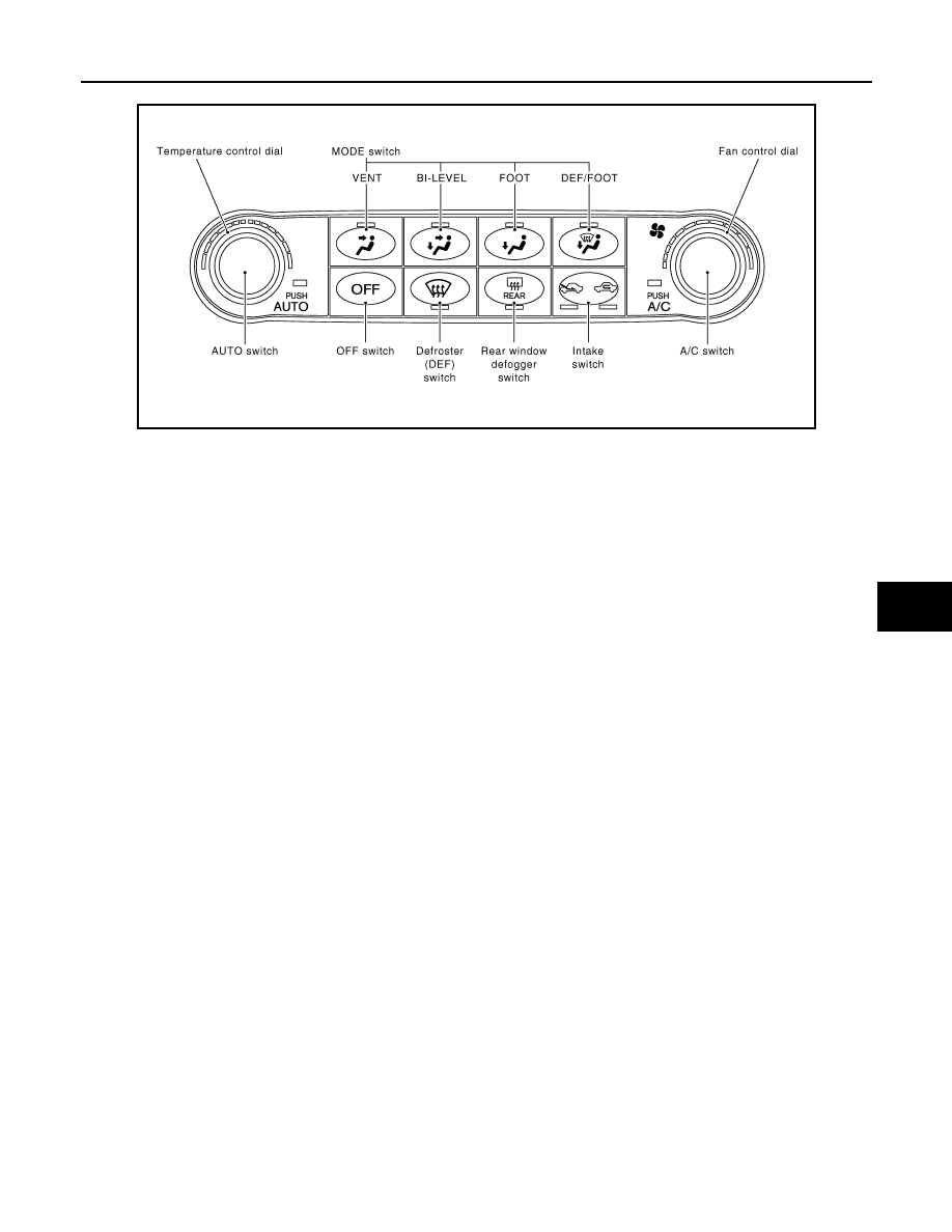
Preset Switch
MODE Switch
The air discharge outlets is controlled with these switches.
Temperature Control Dial (Potentio Temperature Control)
The set temperature is increased or decreased with this dial.
AUTO Switch
• The compressor, intake doors, air mix doors, mode doors and blower speed are automatically controlled so
that the in-vehicle temperature will reach, and be maintained at the set temperature selected by the operator.
• When pressing AUTO switch, air inlet, air outlet, fan speed, and discharge air temperature are automatically
controlled.
Defroster (DEF) Switch
Mode doors are set to the defrost position with this switch. Also, intake doors are set to the outside air position,
and compressor turns ON.
A/C Switch
Compressor is ON or OFF with this switch.
(Pressing the A/C switch when the A/C switch is ON turns OFF the A/C switch and compressor.)
Fan Control Dial
The blower speed is manually controlled with this dial. Seven speeds are available for manual control (as
shown on the display screen).
OFF Switch
Compressor and blower are OFF, air inlet is set to FRE, and mode position is set to foot position.
Rear Window Defogger Switch
When indicator is ON, rear window is defogged.
Intake Switch
• When intake switch is ON, FRE indicator turns ON, and air inlet is fixed to FRE.
• When intake switch is pressed again, REC indicator turns ON, and air inlet is fixed to REC.
• When intake switch is pressed for approximately 1.5 seconds or longer, FRE and REC indicators blink twice.
Then, automatic control mode is entered. Inlet status is displayed by indicator even during automatic con-
trolled.
• When FRE indicator is turned ON, shifting mode position to D/F or DEF, or when compressor is turned from
ON to OFF, intake switch is automatically turned OFF (fixed to FRE mode). REC mode can be re-entered by
pressing intake switch again, and then compressor is turned ON. (Except D/F or DEF position)
JSIIA0767GB
Нет комментариевНе стесняйтесь поделиться с нами вашим ценным мнением.
Текст