Infiniti EX35. Manual — part 201
AV
SIDE CAMERA LH IMAGE SIGNAL CIRCUIT
AV-585
< COMPONENT DIAGNOSIS >
[BOSE AUDIO WITH NAVIGATION]
C
D
E
F
G
H
I
J
K
L
M
B
A
O
P
4.
Check continuity between around view monitor control unit harness connector and ground.
Is inspection result normal?
YES
>> GO TO 4.
NO
>> Repair harness or connector.
4.
CHECK SIDE CAMERA LH IMAGE SIGNAL
1.
Connect around view monitor control unit connector and door mirror (driver side) connector.
2.
Turn ignition switch ON.
3.
Check signal between around view monitor control unit harness connector.
Is inspection result normal?
YES
>> Replace around view monitor control unit.
NO
>> Replace side camera LH.
Around view monitor control
unit
Door mirror (driver side)
Continuity
Connector
Terminals
Connector
Terminals
B45
51
D3
5
Existed
52
17
Around view monitor control
unit
Ground
Continuity
Connector
Terminals
B45
51, 52
Not existed
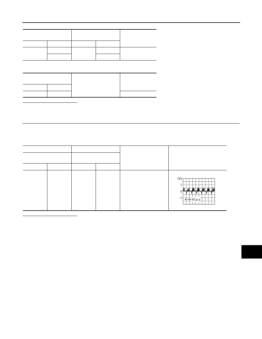
(+)
(
−
)
Condition
Reference value
Around view monitor control
unit
Around view monitor control
unit
Connector
Terminal
Connector
Terminal
B45
51
B45
52
“CAMERA” switch is ON or
shift position is “R”.
JSNIA0834GB
AV-586
< COMPONENT DIAGNOSIS >
[BOSE AUDIO WITH NAVIGATION]
SIDE CAMERA RH COMMUNICATION SIGNAL CIRCUIT
SIDE CAMERA RH COMMUNICATION SIGNAL CIRCUIT
Description
INFOID:0000000003513840
• Around view monitor control unit supplies to the front camera, rear camera and side camera. And then it
superimpose the images from each camera and outputs then to the display unit.
• Superimpose the guiding lines, predicted course line and sonar indicator to the camera image that outputs to
the display unit.
• Around view monitor control unit performs the reception/transmission of communication signal with each
camera.
Diagnosis Procedure
INFOID:0000000003455044
1.
CHECK CONTINUITY COMMUNICATION SIGNAL CIRCUIT
1.
Turn ignition switch OFF.
2.
Disconnect around view monitor control unit connector and door mirror (passenger side) connector.
3.
Check continuity between around view monitor control unit harness connector and door mirror (passenger
side) harness connector.
4.
Check continuity between around view monitor control unit harness connector and ground.
Is inspection result normal?
YES
>> GO TO 2.
NO
>> Repair harness or connector.
2.
CHECK COMMUNICATION SIGNAL
1.
Connect around view monitor control unit connector and door mirror (passenger side) connector.
2.
Turn ignition switch ON.
3.
Check signal between around view monitor control unit harness connector and ground.
Is inspection result normal?
YES
>> Replace around view monitor control unit.
NO
>> Replace side camera RH.
Around view monitor control
unit
Door mirror
(passenger side)
Continuity
Connector
Terminal
Connector
Terminal
B46
33
D33
3
Existed
Around view monitor control
unit
Ground
Continuity
Connector
Terminal
B46
33
Not existed
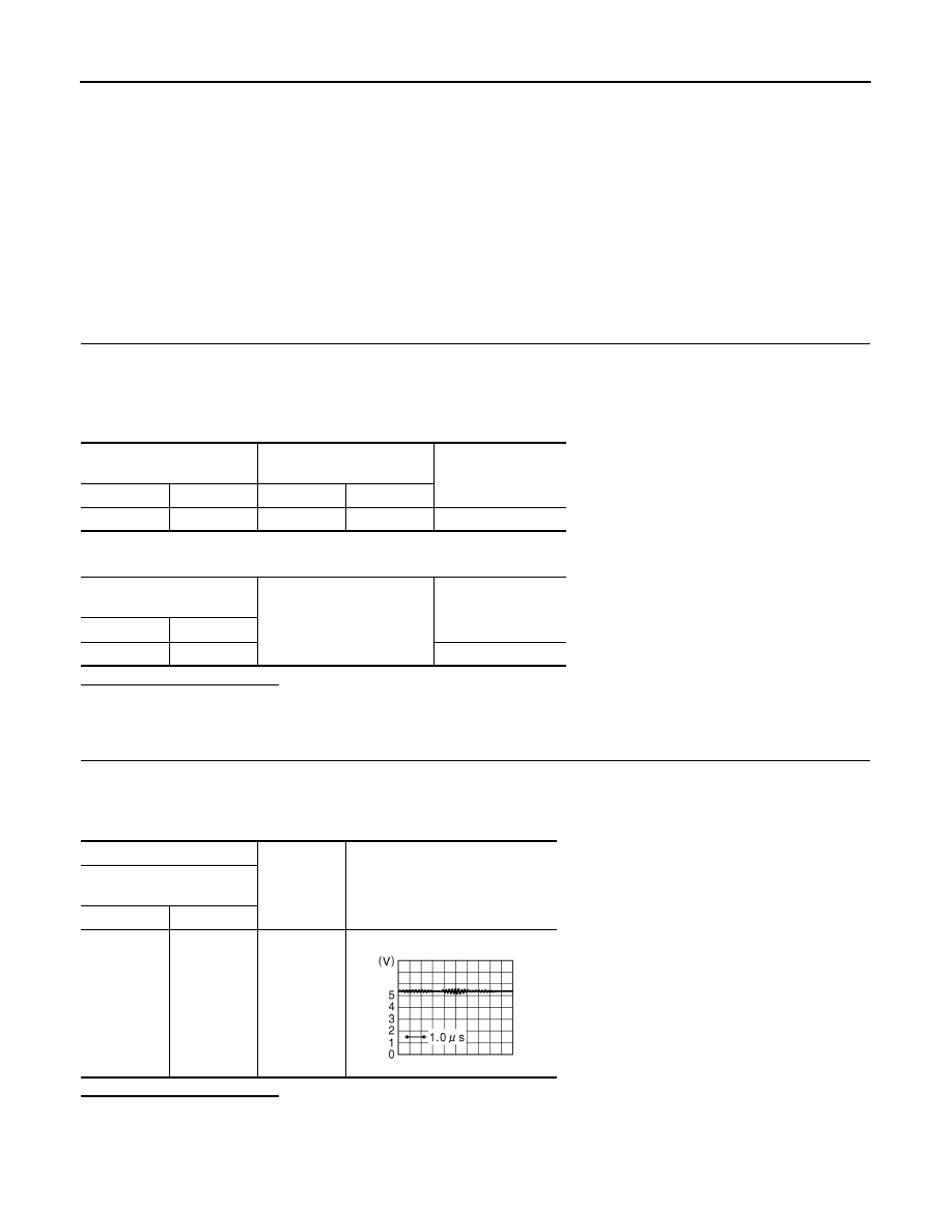
(+)
(
−
)
Reference value
Around view monitor control
unit
Connector
Terminal
B46
33
Ground
JSNIA0836GB
AV
SIDE CAMERA RH IMAGE SIGNAL CIRCUIT
AV-587
< COMPONENT DIAGNOSIS >
[BOSE AUDIO WITH NAVIGATION]
C
D
E
F
G
H
I
J
K
L
M
B
A
O
P
SIDE CAMERA RH IMAGE SIGNAL CIRCUIT
Description
INFOID:0000000003513841
• Around view monitor control unit supplies to the front camera, rear camera and side camera. And then it
superimpose the images from each camera and outputs then to the display unit.
• Superimpose the guiding lines, predicted course line and sonar indicator to the camera image that outputs to
the display unit.
• Around view monitor control unit performs the reception/transmission of communication signal with each
camera.
Diagnosis Procedure
INFOID:0000000003455046
1.
CHECK CONTINUITY SIDE CAMERA RH POWER SUPPLY AND GROUND CIRCUIT
1.
Turn ignition switch OFF.
2.
Disconnect control unit connector and door mirror (passenger side) connector.
3.
Check continuity between around view monitor control unit harness connector and door mirror (passenger
side) harness connector.
4.
Check continuity between around view monitor control unit harness connector and ground.
Is inspection result normal?
YES
>> GO TO 2.
NO
>> Repair harness or connector.
2.
CHECK VOLTAGE SIDE CAMERA RH POWER SUPPLY
1.
Connect around view monitor control unit connector and door mirror (passenger side) connector.
2.
Turn ignition switch ON.
3.
Check voltage between around view monitor control unit harness connector and ground.
Is inspection result normal?
YES
>> GO TO 3.
NO
>> Replace around view monitor control unit.
3.
CHECK CONTINUITY SIDE CAMERA RH IMAGE SIGNAL CIRCUIT
1.
Turn ignition switch OFF.
2.
Disconnect around view monitor control unit connector and door mirror (passenger side) connector.
3.
Check continuity between around view monitor control unit harness connector and door mirror (passenger
side) harness connector.
Around view monitor control
unit
Door mirror
(passenger side)
Continuity
Connector
Terminals
Connector
Terminals
B46
32
D33
18
Existed
34
6
Around view monitor control
unit
Ground
Continuity
Connector
Terminal
B46
34
Not existed
(+)
(
−
)
Condition
Voltage
(Approx.)
Around view monitor control
unit
Connector
Terminal
B46
34
Ground
“CAMERA” switch is ON or
shift position is “R”.
6.0 V
AV-588
< COMPONENT DIAGNOSIS >
[BOSE AUDIO WITH NAVIGATION]
SIDE CAMERA RH IMAGE SIGNAL CIRCUIT
4.
Check continuity between around view monitor control unit harness connector and ground.
Is inspection result normal?
YES
>> GO TO 4.
NO
>> Repair harness or connector.
4.
CHECK SIDE CAMERA RH IMAGE SIGNAL
1.
Connect around view monitor control unit connector and door mirror (passenger side) connector.
2.
Turn ignition switch ON.
3.
Check signal between around view monitor control unit harness connector.
Is inspection result normal?
YES
>> Replace around view monitor control unit.
NO
>> Replace side camera RH.
Around view monitor control
unit
Door mirror
(passenger side)
Continuity
Connector
Terminals
Connector
Terminals
B46
29
D33
5
Existed
30
17
around view monitor control
unit
Ground
Continuity
Connector
Terminals
B46
29, 30
Not existed
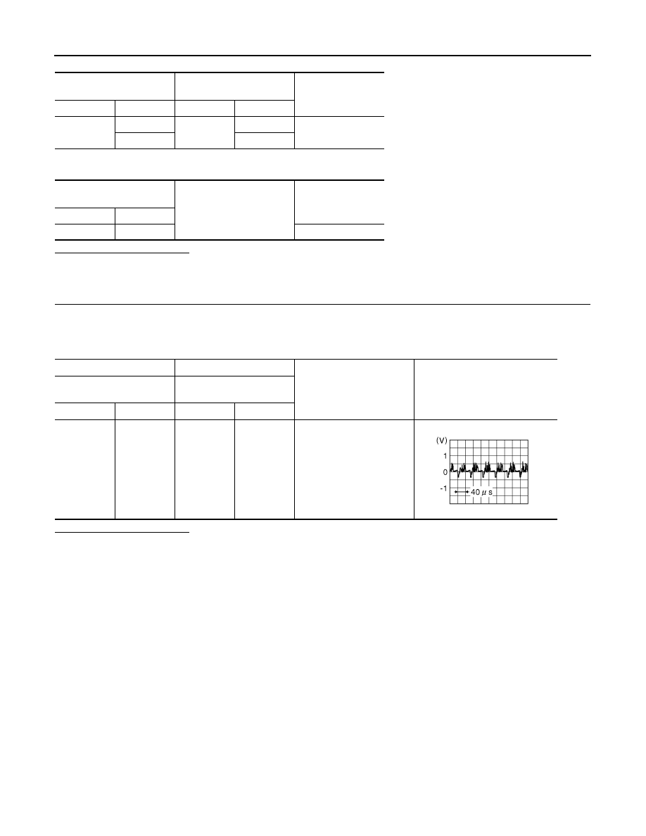
(+)
(
−
)
Condition
Reference value
Around view monitor control
unit
Around view monitor control
unit
Connector
Terminal
Connector
Terminal
B46
29
B46
30
“CAMERA” switch is ON or
shift position is “R”.
JSNIA0834GB
Нет комментариевНе стесняйтесь поделиться с нами вашим ценным мнением.
Текст