Infiniti EX35. Manual — part 895
COMPRESSOR
HA-39
< ON-VEHICLE REPAIR >
C
D
E
F
G
H
J
K
L
M
A
B
HA
N
O
P
ON-VEHICLE REPAIR
COMPRESSOR
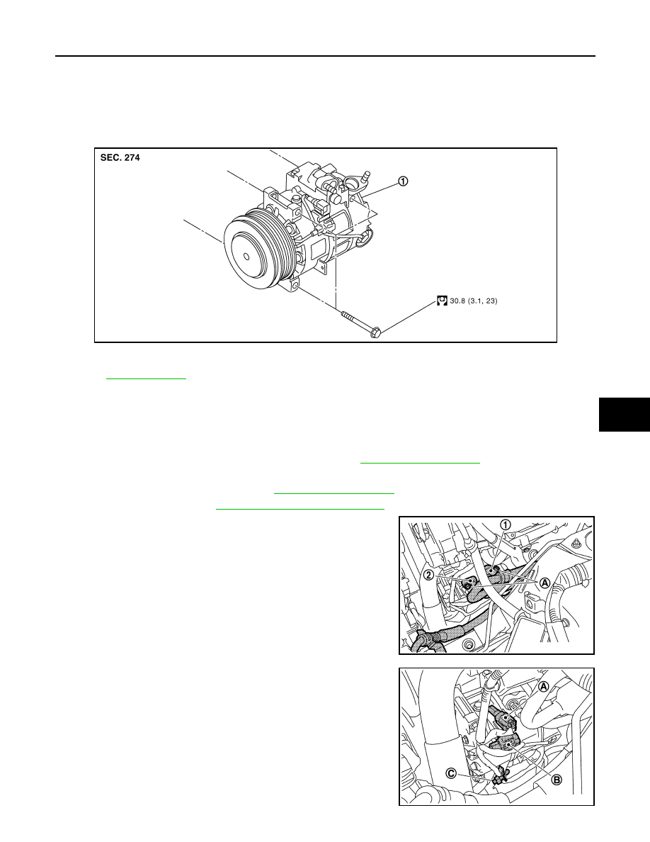
Exploded View
INFOID:0000000003545476
Removal and Installation
INFOID:0000000003545477
REMOVAL
1.
Use a refrigerant collecting equipment (for HFC-134a) to discharge the refrigerant.
2.
Remove air cleaner case (LH) and air duct (LH). Refer to
.
3.
Remove engine undercover, using power tools.
4.
Remove cooling fan assembly. Refer to
5.
Remove drive belt. Refer to
EM-13, "Removal and Installation"
.
6.
Remove mounting nuts (A) from low-pressure flexible hose (1)
and high-pressure flexible hose (2).
CAUTION:
Cap or wrap the joint of the A/C piping and compressor with
suitable material such as vinyl tape to avoid the entry of air.
7.
Disconnect compressor (ECV) connector (A).
8.
Disconnect compressor (magnet clutch) connector (B).
9.
Remove harness clip (C)
1.
Compressor
Refer to
JSIIA0011GB
JPIIA0685ZZ
JPIIA0686ZZ
HA-40
< ON-VEHICLE REPAIR >
COMPRESSOR
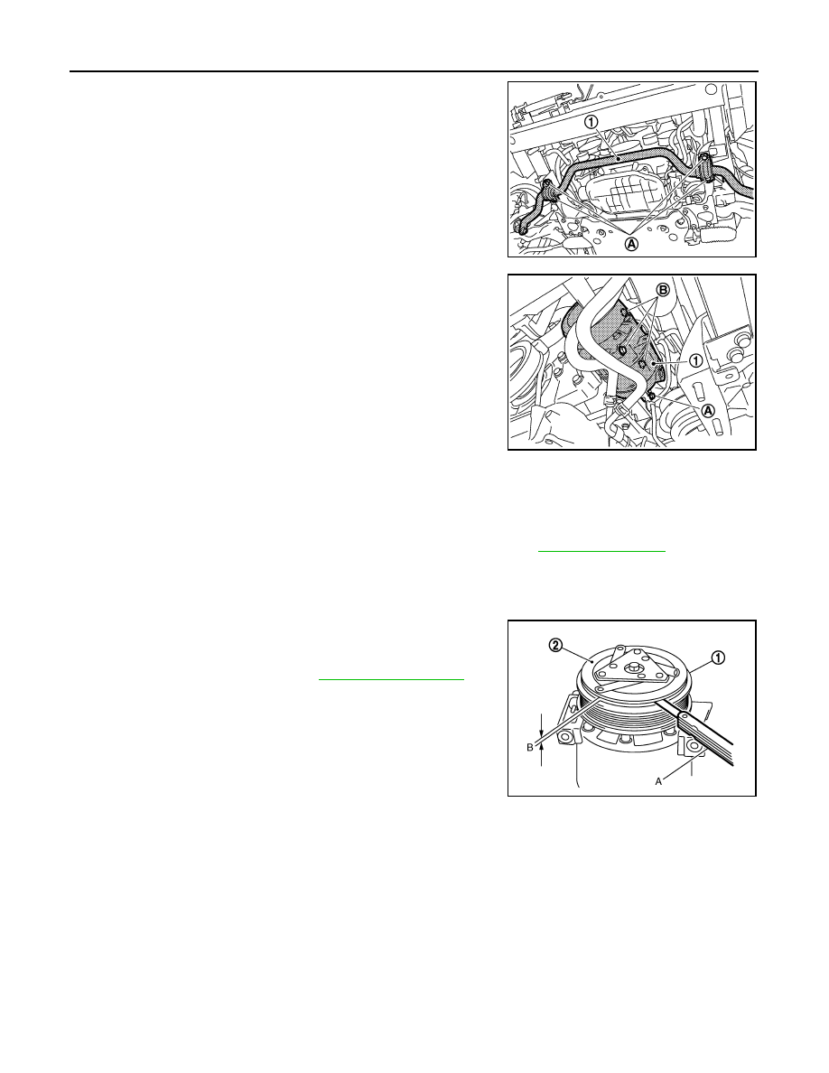
10. Remove mounting nuts (A), and stabilizer (1) a position without
the hindrance for work.
11. Remove mounting bolts (A), and then remove harness bracket.
12. Remove mounting bolts (B) from compressor (1), using power
tools.
13. Remove compressor downward of the vehicle.
INSTALLATION
Installation is basically the reverse order of removal.
CAUTION:
• Replace O-rings with new ones. Then apply compressor oil to them when installing.
• Check for leakages when recharging refrigerant.
• Check tension of the drive belt after installing compressor. Refer to
Inspection
INFOID:0000000003545478
CHECK DISC TO PULLEY CLEARANCE
Check the clearance (B) between pulley assembly (1) and clutch
disc (2) along the entire periphery with a feeler gauge (A).
Replace compressor if specified clearance is not obtained.
JPIIA0687ZZ
JPIIA0688ZZ
Standard
: Refer to
JSIIA0087ZZ
LOW-PRESSURE FLEXIBLE HOSE
HA-41
< ON-VEHICLE REPAIR >
C
D
E
F
G
H
J
K
L
M
A
B
HA
N
O
P
LOW-PRESSURE FLEXIBLE HOSE
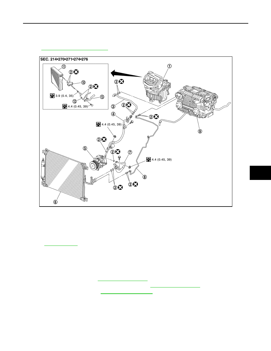
Exploded View
INFOID:0000000003545479
HA-13, "Refrigerant Connection"
.
Removal and Installation
INFOID:0000000003545480
REMOVAL
1.
Use a refrigerant collecting equipment (for HFC-134a) to discharge the refrigerant.
2.
Remove engine cover. Refer to
.
3.
Remove air cleaner case (LH) and air duct (LH). Refer to
.
4.
Remove cowl top cover. Refer to
1.
Blower unit
2.
O-ring
3.
Low-pressure pipe 2
4.
Low-pressure flexible hose
5.
Compressor
6.
Condenser
7.
High-pressure flexible hose
8.
High-pressure pipe 1
9.
Heater & cooling unit assembly
10. Expansion valve
11.
Evaporator
12. High-pressure pipe 2
13. Low-pressure pipe 1
Refer to
JPIIA0684GB
HA-42
< ON-VEHICLE REPAIR >
LOW-PRESSURE FLEXIBLE HOSE
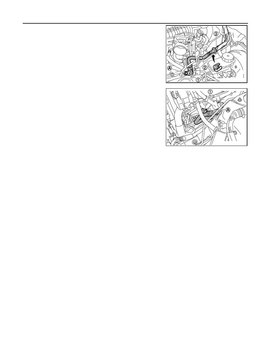
5.
Remove mounting bolt (A) from low-pressure flexible hose
bracket (1).
6.
Disconnect one-touch joint between low-pressure flexible hose
(2) and low-pressure pipe 2 (3) with disconnector (B) (SST:
9253089916).
CAUTION:
Cap or wrap the joint of the A/C piping with suitable mate-
rial such as vinyl tape to avoid the entry of air.
7.
Remove mounting nut (A) from low-pressure flexible hose (1).
CAUTION:
Cap or wrap the joint of the A/C piping and compressor with
suitable material such as vinyl tape to avoid the entry of air.
8.
Remove low-pressure flexible hose.
INSTALLATION
Installation is basically the reverse order of removal.
CAUTION:
• Replace O-rings with new ones. Then apply compressor oil to them when installing.
• Female-side piping connection is thin and easy to deform. Slowly insert the male-side piping
straight in axial direction.
• Insert piping securely until a click is heard.
• After piping connection is completed, pull male-side piping by hand to make sure that connection
does not come loose.
• Check for leakages when recharging refrigerant.
JPIIA0689ZZ
JPIIA0690ZZ
Нет комментариевНе стесняйтесь поделиться с нами вашим ценным мнением.
Текст