Infiniti EX35. Manual — part 717
CAMSHAFT
EM-67
< ON-VEHICLE REPAIR >
C
D
E
F
G
H
I
J
K
L
M
A
EM
N
P
O
CAMSHAFT
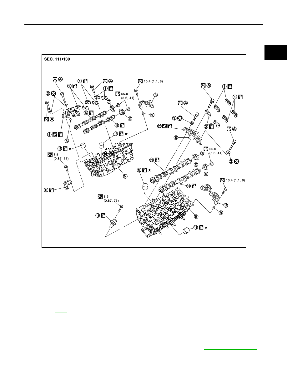
Exploded View
INFOID:0000000003139119
Removal and Installation
INFOID:0000000003139120
REMOVAL
1.
Remove front timing chain case, camshaft sprocket and timing chain. Refer to
.
2.
Remove fuel sub tube. Refer to
.
1.
Camshaft bracket (No. 3, 4)
2.
Camshaft bracket (No. 2)
3.
Seal washer
4.
Camshaft bracket (No. 1) (bank 1)
5.
Dowel pin
6.
Camshaft (EXH) (bank 1)
7.
Camshaft signal plate (EXH)
8.
Camshaft sensor bracket (bank 1)
9.
Dowel pin
10. Camshaft signal plate (INT)
11.
Camshaft (INT) (bank 1)
12. Valve lifter
13.
Timing chain tensioner (secondary)
(bank 1)
14.
Cylinder head (bank 1)
15.
Timing chain tensioner (secondary)
(bank 2)
16. Cylinder head (bank 2)
17.
Camshaft sensor bracket
18. Camshaft (EXH)
19. Camshaft signal plate (EXH)
20.
Camshaft signal plate (INT)
21. Camshaft (INT)
22. Camshaft bracket (No. 1) (bank 2)
A.
Refer to
Refer to
for symbols in the figure.
JPBIA1901GB
EM-68
< ON-VEHICLE REPAIR >
CAMSHAFT
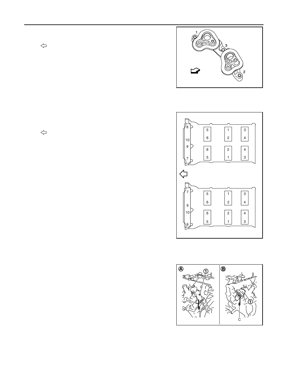
3.
Loosen camshaft sensor bracket bolts in reverse order as
shown in the figure.
NOTE:
The order of loosening bolts is the same for bank 1 and bank 2.
4.
Remove camshaft brackets.
• Mark camshafts, camshaft brackets and bolts so they are placed in the same position and direction for
installation.
• Equally loosen camshaft bracket bolts in several steps in
reverse order as shown in the figure.
5.
Remove camshaft.
6.
Remove valve lifter.
• Identify installation positions, and store them without mixing them up.
7.
Remove timing chain tensioners (secondary) (1) from cylinder
head.
• Remove timing chain tensioners (secondary) with its stopper
pin (C) attached.
NOTE:
Stopper pin should be attached when timing chain (secondary)
is removed.
INSTALLATION
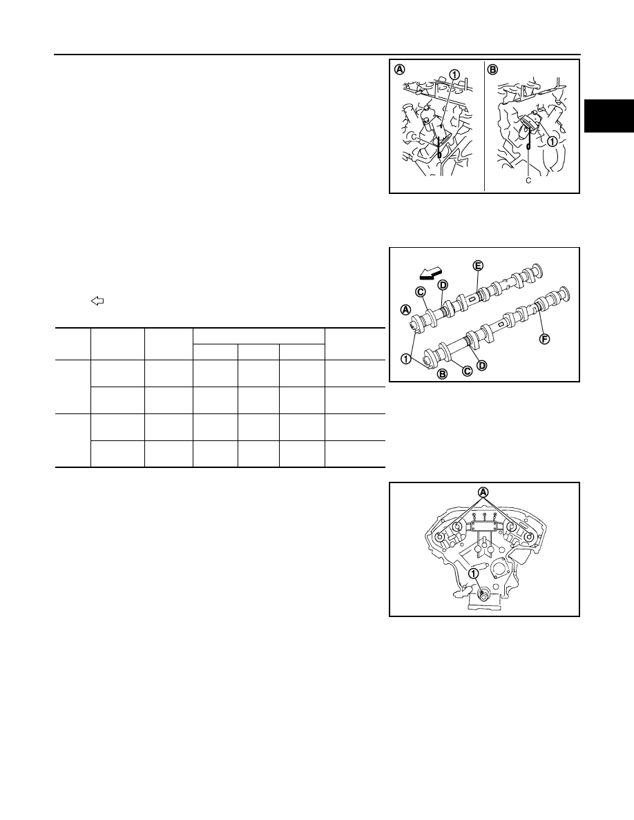
1.
Install timing chain tensioners (secondary) on both sides of cylinder head.
: Engine front
JPBIA1960ZZ
: Engine front
JPBIA0257ZZ
A
: Bank 1
B
: Bank 2
JPBIA0121ZZ
CAMSHAFT
EM-69
< ON-VEHICLE REPAIR >
C
D
E
F
G
H
I
J
K
L
M
A
EM
N
P
O
• Install timing chain tensioners (1) with its stopper pin (C)
attached.
2.
Install valve lifter.
• Install it in the original position.
3.
Install camshafts.
• Follow your identification marks made during removal, or fol-
low the identification marks that are present on new camshafts
for proper placement and direction.
• Install camshaft so that dowel pin (A) on front end face are
positioned as shown in the figure. (No. 1 cylinder TDC on its
compression stroke)
NOTE:
Though camshaft does not stop at the portion as shown in the
figure, for the placement of cam nose, it is generally accepted
camshaft is placed for the same direction of the figure.
Bank 1 side (A)
: Sliding part facing downward
Bank 2 side (B)
: Sliding part facing upward
JPBIA0121ZZ
: Engine front
Bank
INT/EXH
Dowel pin
(1)
Paint marks
Identification
mark (C)
M1 (E)
M2 (F)
M3 (D)
1
EXH (B)
Yes
No
Green
Light
blue
1F
INT (A)
Yes
Green
No
Light
blue
1E
2
INT (A)
Yes
Green
No
Light
blue
1G
EXH (B)
Yes
No
Green
Light
blue
1H
JPBIA1191ZZ
1
: Crankshaft key
JPBIA0094ZZ
EM-70
< ON-VEHICLE REPAIR >
CAMSHAFT
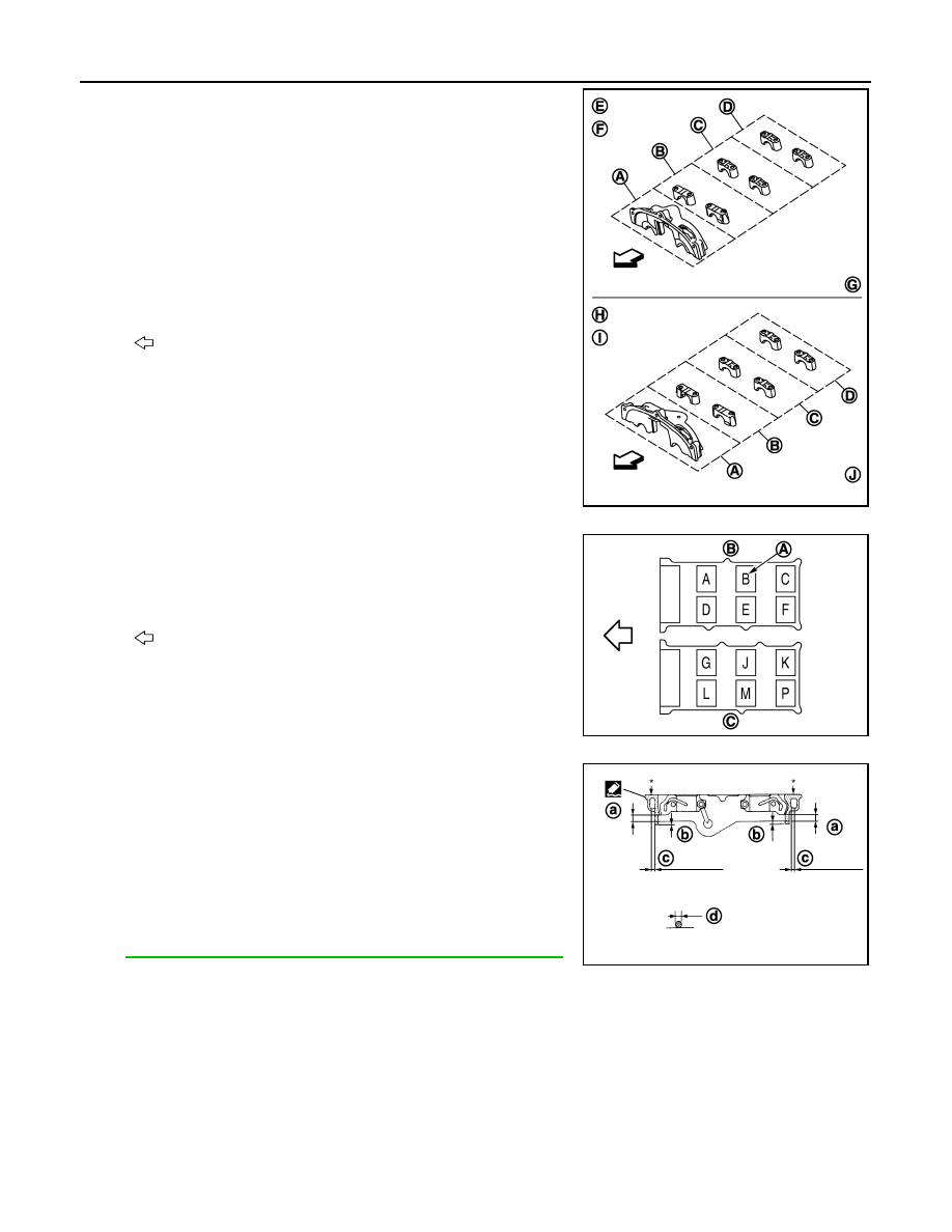
4.
Install camshaft brackets.
• Remove foreign material completely from camshaft bracket
backside and from cylinder head installation face.
• Install camshaft bracket in original position and direction as
shown in figure.
• Install camshaft brackets (No. 2 to 4) aligning the stamp marks
(A) as shown in the figure.
NOTE:
There are no identification marks indicating bank 1 and bank 2
for camshaft bracket (No. 1).
• Apply liquid gasket to mating surface of camshaft bracket (No.
1) as shown on both bank 1 and bank 2.
Use Genuine RTV Silicone Sealant or equivalent. Refer to
GI-15, "Recommended Chemical Products and Sealants"
.
A
: No. 1
B
: No. 2
C
: No. 3
D
: No. 4
E
: Camshaft brackets (bank 1)
F
: Exhaust side
G
: Intake side
H
: Camshaft brackets (bank 2)
I
: Intake side
J
: Exhaust side
: Engine front
JPBIA0258ZZ
B
: Bank 1
C
: Bank 2
: Engine front
JPBIA0272ZZ
a
: 8.5 mm (0.335 in)
b
: 2 mm (0.08 in)
c
: Clearance 5 mm (0.20 in)
d
:
φ
2.5 mm (0.098 in)
*
: Apply liquid gasket to rear timing chain side
JPBIA0255ZZ
Нет комментариевНе стесняйтесь поделиться с нами вашим ценным мнением.
Текст