Infiniti EX35. Manual — part 718

CAMSHAFT
EM-71
< ON-VEHICLE REPAIR >
C
D
E
F
G
H
I
J
K
L
M
A
EM
N
P
O
• Apply liquid gasket to camshaft bracket (No. 1) contact surface
on the rear timing chain case backside as shown on both bank
1 and bank 2.
Use Genuine RTV Silicone Sealant or equivalent. Refer to
GI-15, "Recommended Chemical Products and Sealants"
.
CAUTION:
For camshaft bracket (No. 1) near installation position,
and install it without disturbing the liquid gasket applied
to the surfaces.
5.
Tighten camshaft bracket bolts in the following steps, in numeri-
cal order as shown in the figure.
a.
Tighten No. 7 to 10 in numerical order as shown.
b.
Tighten No. 1 to 6 in numerical order as shown.
c.
Tighten No. 1 to 10 in numerical order as shown.
d.
Tighten No. 1 to 10 in numerical order as shown.
6.
Tighten camshaft sensor bracket bolts in numerical order as
shown in the figure.
NOTE:
The order of tightening bolts is the same for bank 1 and bank 2.
7.
Inspect and adjust the valve clearance. Refer to
EM-18, "Inspection and Adjustment"
.
8.
Install in the reverse order of removal after this step.
Inspection
INFOID:0000000003139121
INSPECTION AFTER REMOVAL
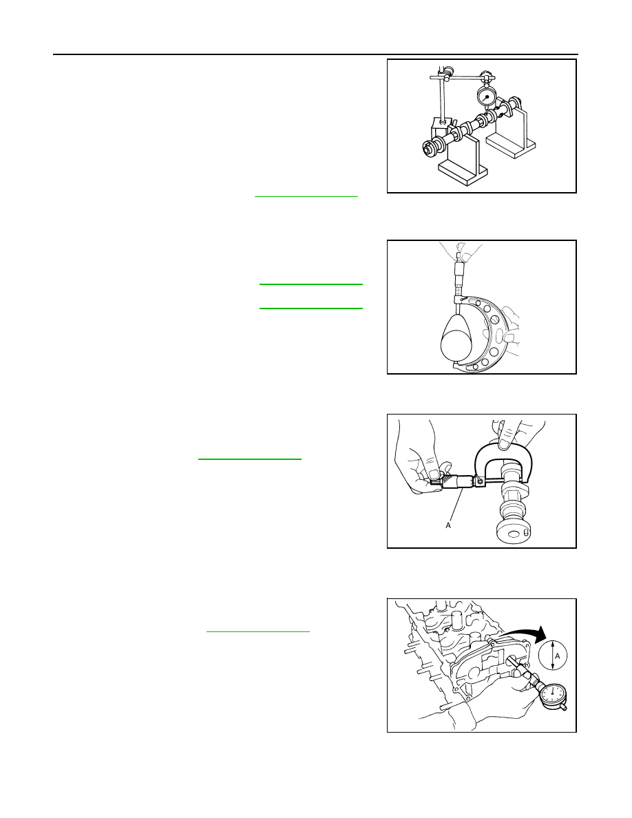
Camshaft Runout
1
: Rear timing chain case
a
:
φ
3.9 mm (0.154 in)
JPBIA0881ZZ
: Engine front
: 1.96 N·m (0.20 kg-m, 1 ft-lb)
: 1.96 N·m (0.20 kg-m, 1 ft-lb)
: 5.88 N·m (0.60 kg-m, 4 ft-lb)
: 10.4 N·m (1.1 kg-m, 8 ft-lb)
JPBIA0257ZZ
: Engine front
JPBIA1960ZZ
EM-72
< ON-VEHICLE REPAIR >
CAMSHAFT
1.
Put V-block on precise flat table, and support No. 2 and 4 jour-
nals of camshaft.
CAUTION:
Never support No. 1 journal (on the side of camshaft
sprocket) because it has a different diameter from the other
three locations.
2.
Set a dial indicator vertically to No. 3 journal.
3.
Turn camshaft to one direction with hands, and measure the
camshaft runout on a dial indicator. (Total indicator reading)
4.
If it exceeds the limit, replace camshaft.
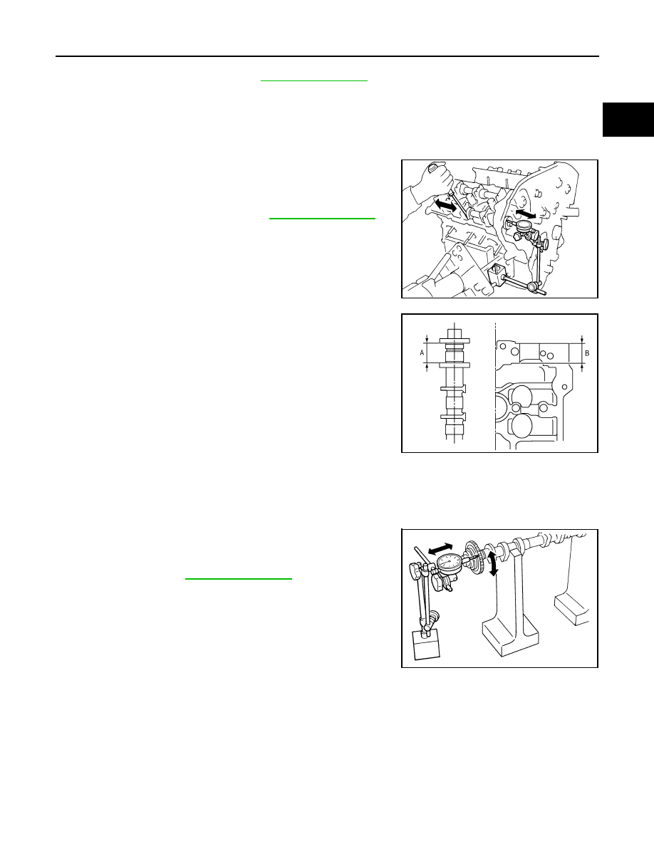
Camshaft Cam Height
1.
Measure the camshaft cam height with a micrometer.
2.
If wear exceeds the limit, replace camshaft.
Camshaft Journal Oil Clearance
CAMSHAFT JOURNAL DIAMETER
• Measure the outer diameter of camshaft journal with a micrometer
(A).
CAMSHAFT BRACKET INNER DIAMETER
• Tighten camshaft bracket bolt with the specified torque. Refer to “INSTALLATION” for the tightening proce-
dure.
• Measure inner diameter (A) of camshaft bracket with a bore gauge.
CAMSHAFT JOURNAL OIL CLEARANCE
• (Oil clearance) = (Camshaft bracket inner diameter) – (Camshaft journal diameter).
Standard and limit
: Refer to
PBIC0929E
Standard cam height
: Refer to
(Intake and exhaust)
Cam wear limit
: Refer to
EMQ0072D
Standard
: Refer to
JPBIA0122ZZ
Standard
: Refer to
PBIC1645E
CAMSHAFT
EM-73
< ON-VEHICLE REPAIR >
C
D
E
F
G
H
I
J
K
L
M
A
EM
N
P
O
• If the calculated value exceeds the limit, replace either or both camshaft and cylinder head.
NOTE:
Camshaft brackets cannot be replaced as single parts, because there are machined together with cylinder
head. Replace whole cylinder head assembly.
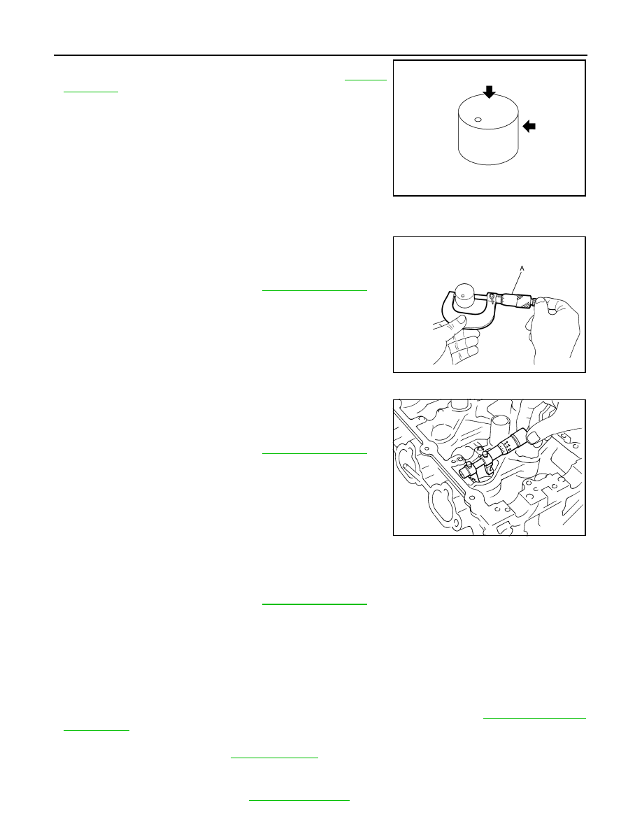
Camshaft End Play
• Install a dial indicator in thrust direction on front end of camshaft.
Measure the end play of a dial indicator when camshaft is moved
forward/backward (in direction to axis).
• Measure the following parts if out of the limit.
- Dimension “A” for camshaft No. 1 journal
- Dimension “B” for cylinder head No. 1 journal bearing
• Refer to the standards above, and then replace camshaft and/or
cylinder head.
Camshaft Sprocket Runout
1.
Put V-block on precise flat table, and support No. 2 and 4 journals of camshaft.
CAUTION:
Never support No. 1 journal (on the side of camshaft sprocket) because it has a different diameter
from the other three locations.
2.
Measure the camshaft sprocket runout with a dial indicator.
(Total indicator reading)
• If it exceeds the limit, replace camshaft sprocket.
Valve Lifter
Standard and limit
: Refer to
Standard and limit
: Refer to
.
SEM864E
Standard
: 27.500 - 27.548 mm (1.0827 - 1.0846 in)
Standard
: 27.360 - 27.385 mm (1.0772 - 1.0781 in)
KBIA2404J
Limit
: Refer to
PBIC0930E
EM-74
< ON-VEHICLE REPAIR >
CAMSHAFT
Check if surface of valve lifter has any wear or cracks.
• If anything above is found, replace valve lifter. Refer to
.
Valve Lifter Clearance
VALVE LIFTER OUTER DIAMETER
• Measure the outer diameter at 1/2 height of valve lifter with a
micrometer (A) since valve lifter is in barrel shape.
VALVE LIFTER HOLE DIAMETER
• Measure the inner diameter of valve lifter hole of cylinder head with
an inside micrometer.
VALVE LIFTER CLEARANCE
• (Valve lifter clearance) = (Valve lifter hole diameter) – (Valve lifter outer diameter)
• If the calculated value is out of the standard, referring to each standard of valve lifter outer diameter and
valve lifter hole diameter, replace either or both valve lifter and cylinder head.
INSPECTION AFTER INSTALLATION
Inspection of Camshaft Sprocket (INT) Oil Groove
CAUTION:
• Perform this inspection only when DTC P0011 is detected in self-diagnostic results of CONSULT-III
and it is directed according to inspection procedure of EC section. Refer to
• Check when engine is cold so as to prevent burns from the splashing engine oil.
1.
Check engine oil level. Refer to
.
2.
Perform the following procedure so as to prevent the engine from being unintentionally started while
checking.
a.
Release the fuel pressure. Refer to
.
KBIA0182E
Standard
: Refer to
(Intake and exhaust)
JPBIA0125ZZ
Standard
: Refer to
(Intake and exhaust)
SEM867E
Standard
: Refer to
(Intake and exhaust)
Нет комментариевНе стесняйтесь поделиться с нами вашим ценным мнением.
Текст