Infiniti EX35. Manual — part 426
RADIATOR
CO-13
< ON-VEHICLE REPAIR >
C
D
E
F
G
H
I
J
K
L
M
A
CO
N
P
O
ON-VEHICLE REPAIR
RADIATOR
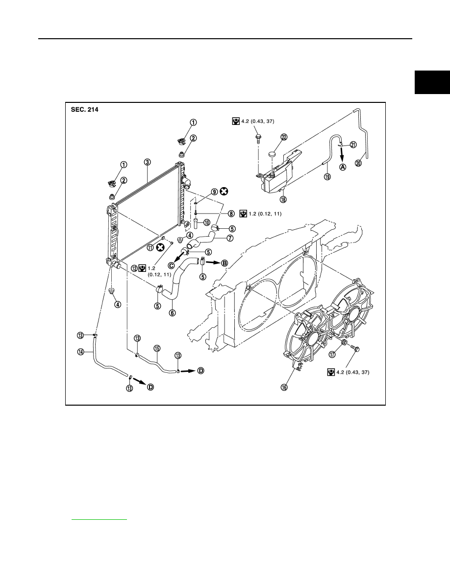
Exploded View
INFOID:0000000003139286
Removal and Installation
INFOID:0000000003139287
REMOVAL
1.
Upper mount bracket
2.
Mounting rubber (upper)
3.
Radiator
4.
Mounting rubber (lower)
5.
Clamp
6.
Radiator hose (lower)
7.
Radiator hose (upper)
8.
Drain plug
9.
O-ring
10. Water drain hose
11.
O-ring
12. Air relief plug
13. Clamp
14. A/T fluid cooler hose
15. A/T fluid cooler hose
16. Cooling fan assembly
17. Grommet
18. Reservoir tank
19. Reservoir tank hose
20. Reservoir tank hose
21. Clamp
22. Reservoir tank cap
A.
To water outlet (front)
B.
To water inlet
C.
To water outlet (front)
D.
To A/T fluid cooler pipe
Refer to
for symbols in the figure.
JPBIA1831GB
CO-14
< ON-VEHICLE REPAIR >
RADIATOR
WARNING:
Never remove radiator cap when engine is hot. Serious burns could occur from high-pressure engine
coolant escaping from water outlet (front). Wrap a thick cloth around the cap. Slowly turn it a quarter
of a turn to release built-up pressure. Carefully remove radiator cap by turning it all the way.
1.
Remove the following parts:
• Engine under cover with power tool.
• Engine cover: Refer to
• Air cleaner case (RH and LH): Refer to
.
• Reservoir tank: Refer to
.
• Hood lock cover, hood lock stay assembly and horn: Refer to
2.
Remove condenser. Refer to
.
3.
Drain engine coolant from radiator. Refer to
.
CAUTION:
• Perform this step when the engine is cold.
• Never spill engine coolant on drive belt.
4.
Disconnect A/T fluid cooler hoses from radiator.
• Install blind plug to avoid leakage of A/T fluid.
5.
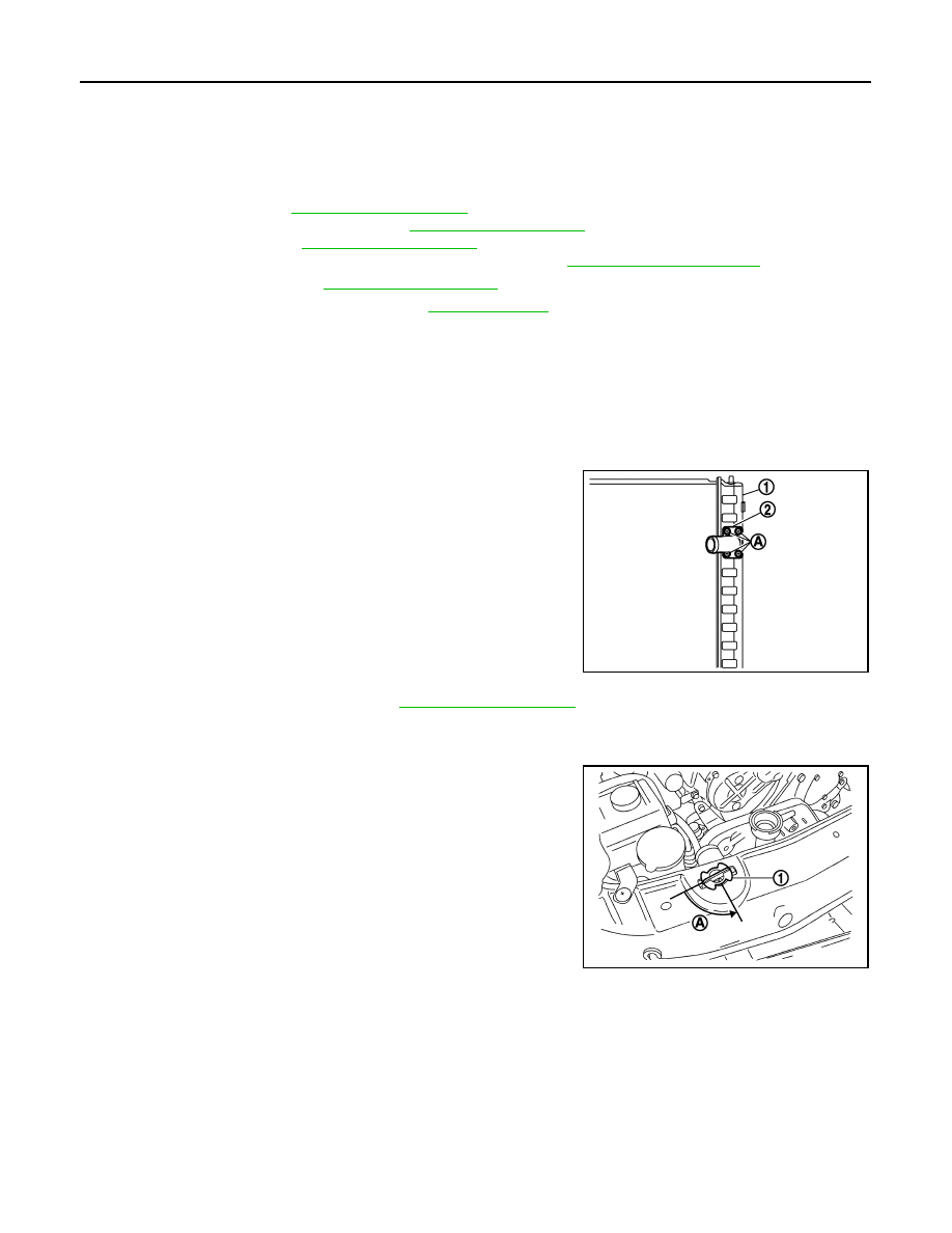
Remove radiator hoses (upper and lower) and reservoir tank hose.
CAUTION:
• Be careful not to allow engine coolant to contact drive belt.
• Never loosen radiator water inlet pipe mounting screw
(A). If loosened, replace radiator (1).
6.
Remove cooling fan assembly. Refer to
CAUTION:
Never damage or scratch radiator core when removing.
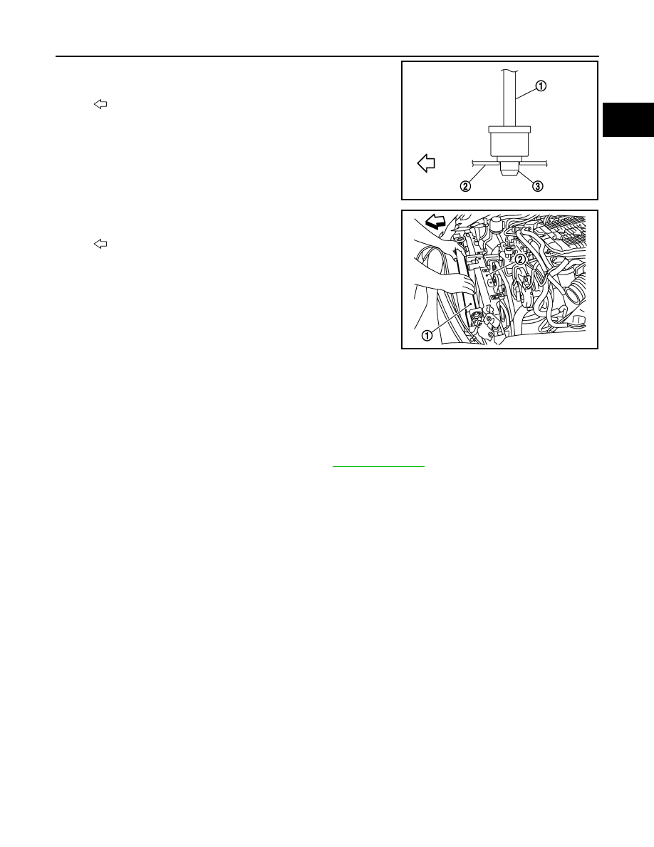
7.
Rotate two radiator upper mount brackets 90 degrees in direc-
tion as shown in the figure, and remove them.
8.
Remove radiator as follows:
CAUTION:
Be careful not to damage radiator core.
2
: Radiator water inlet pipe
JPBIA1832ZZ
1
: Radiator upper mount bracket
A
: Turn 90
°
counterclockwise
JPBIA0105ZZ
RADIATOR
CO-15
< ON-VEHICLE REPAIR >
C
D
E
F
G
H
I
J
K
L
M
A
CO
N
P
O
a.
Lift up and pull the radiator (1) forward, and then remove the
mounting rubber (lower) (3) from the radiator core support (2).
b.
Remove radiator (1) from front of radiator core support (2).
INSTALLATION
Installation is the reverse order of removal.
Inspection
INFOID:0000000003613055
INSPECTION AFTER INSTALLATION
• Check for leakage of engine coolant using the radiator cap tester adapter (commercial service tool) and the
radiator cap tester (commercial service tool). Refer to
.
• Start and warm up the engine. Visually check that there is no leakage of engine coolant and A/T fluid.
: Vehicle front
JPBIA0106ZZ
: Vehicle front
JPBIA0107ZZ
CO-16
< ON-VEHICLE REPAIR >
COOLING FAN
COOLING FAN
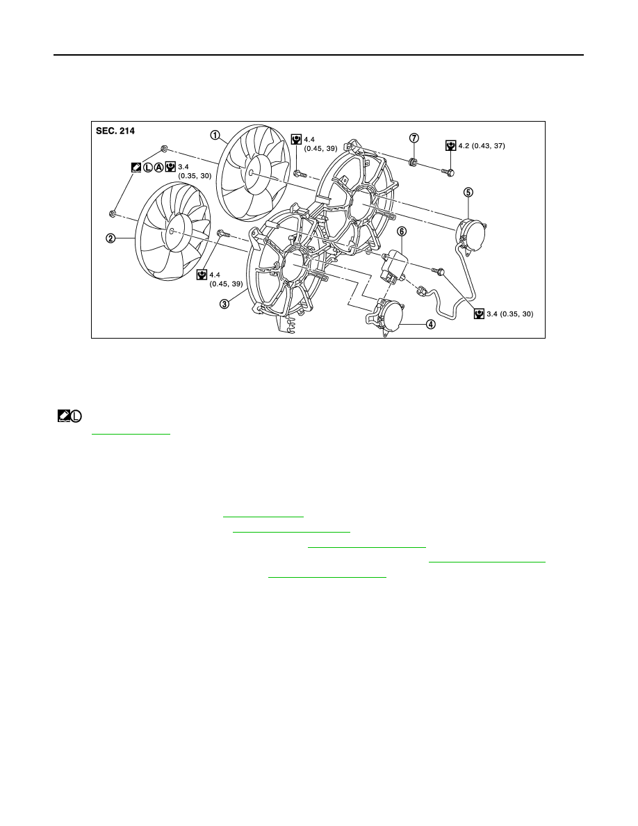
Exploded View
INFOID:0000000003139289
Removal and Installation
INFOID:0000000003139290
REMOVAL
1.
Remove engine under cover with power tool.
2.
Drain engine coolant. Refer to
3.
Remove reservoir tank. Refer to
.
4.
Remove air cleaner case (LH and RH). Refer to
5.
Remove mounting bolt from high pressure flexible hose bracket. Refer to
6.
Remove radiator hose (upper). Refer to
.
7.
Disconnect harness connector from cooling fan control module, and move harness to aside.
8.
Remove cooling fan assembly.
CAUTION:
Be careful not to damage or scratch on radiator core.
INSTALLATION
Note the following, and install in the reverse order of removal.
CAUTION:
Only use genuine parts for cooling fan mounting bolt and observe the specified torque (to prevent
radiator from being damaged).
Disassembly and Assembly
INFOID:0000000003139292
DISASSEMBLY
1.
Disconnect harness connector from cooling fan control module.
2.
Remove cooling fan control module from cooling fan assembly.
CAUTION:
1.
Cooling fan (RH)
2.
Cooling fan (LH)
3.
Fan shroud
4.
Fan motor (LH)
5.
Fan motor (RH)
6.
Cooling fan control module
7.
Grommet
A.
Apply on fan motor shaft
: Apply high strength thread locking sealant or equivalent.
Refer to
for symbols not described on the above.
JPBIA1833GB
Нет комментариевНе стесняйтесь поделиться с нами вашим ценным мнением.
Текст