Infiniti EX35. Manual — part 427
COOLING FAN
CO-17
< ON-VEHICLE REPAIR >
C
D
E
F
G
H
I
J
K
L
M
A
CO
N
P
O
Handle carefully to avoid dropping and shocks.
3.
Remove cooling fan mounting nuts, and then remove the cooling fan (RH and LH).
4.
Remove fan motors (RH and LH).
ASSEMBLY
Note the following, and assemble in the reverse order of disassembly.
CAUTION:
RH and LH cooling fans are different. Be careful not to misassemble them.
• Install each fan in the following position.
• Secure the harness tightly to the fan shroud to prevent the fan rotation area from being loose.
Inspection
INFOID:0000000003139293
INSPECTION AFTER REMOVAL
Check that fan motors operate normally.
NOTE:
Cooling fans are controlled by cooling fan control module. For details, refer to
.
INSPECTION AFTER DISASSEMBLY
Cooling Fan
Inspect cooling fan for crack or unusual bend.
• If anything is found, replace cooling fan.
Right side
: 9 blades
Left side
: 11 blades
CO-18
< ON-VEHICLE REPAIR >
WATER PUMP
WATER PUMP
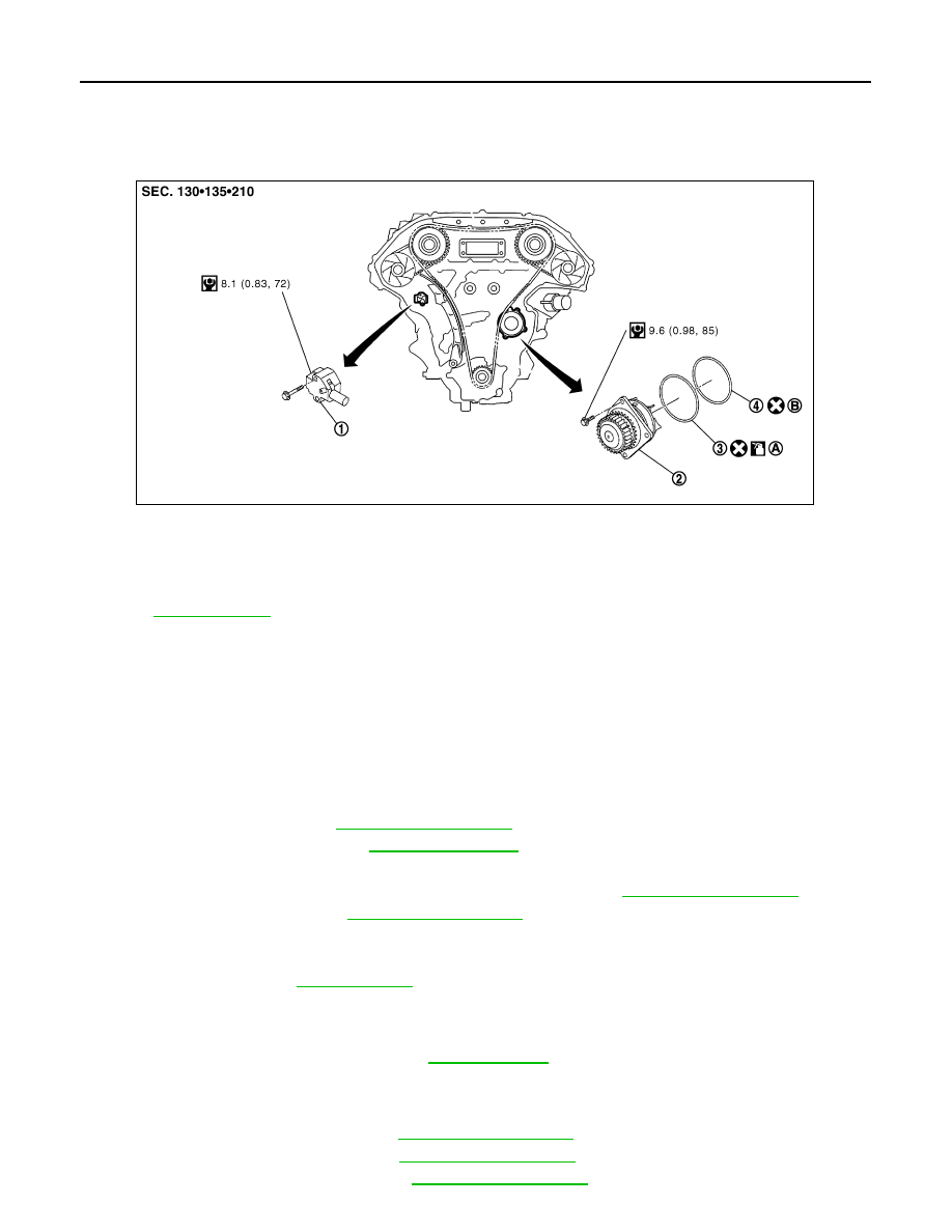
Exploded View
INFOID:0000000003139294
Removal and Installation
INFOID:0000000003139295
CAUTION:
• When removing water pump assembly, be careful not to get engine coolant on drive belt.
• Water pump cannot be disassembled and should be replaced as a unit.
• After installing water pump, connect hose and clamp securely, then check for leakage using the radi-
ator cap tester (commercial service tool) and the radiator cap tester adapter (commercial service
tool).
REMOVAL
1.
Remove engine cover. Refer to
.
2.
Release the fuel pressure. Refer to
.
3.
Disconnect the battery cable from the negative terminal.
4.
Remove air duct and air cleaner case assembly (RH and LH). Refer to
5.
Remove reservoir tank. Refer to
.
6.
Separate engine harness removing their brackets from front timing chain case.
7.
Remove engine undercover with power tool.
8.
Drain engine oil. Refer to
.
CAUTION:
• Perform this step when the engine is cold.
• Never spill engine oil on drive belt.
9.
Drain engine coolant from radiator. Refer to
.
CAUTION:
• Perform this step when the engine is cold.
• Never spill engine coolant on drive belt.
10. Remove radiator hose (lower). Refer to
.
11. Remove cooling fan assembly. Refer to
12. Remove front timing chain case. Refer to
1.
Timing chain tensioner (primary)
2.
Water pump
3.
O-ring
4.
O-ring
A.
Identify with yellow paint mark
B.
Identify with light blue paint mark
Apply engine coolant
Refer to
for symbols in the figure.
JPBIA0270GB
WATER PUMP
CO-19
< ON-VEHICLE REPAIR >
C
D
E
F
G
H
I
J
K
L
M
A
CO
N
P
O
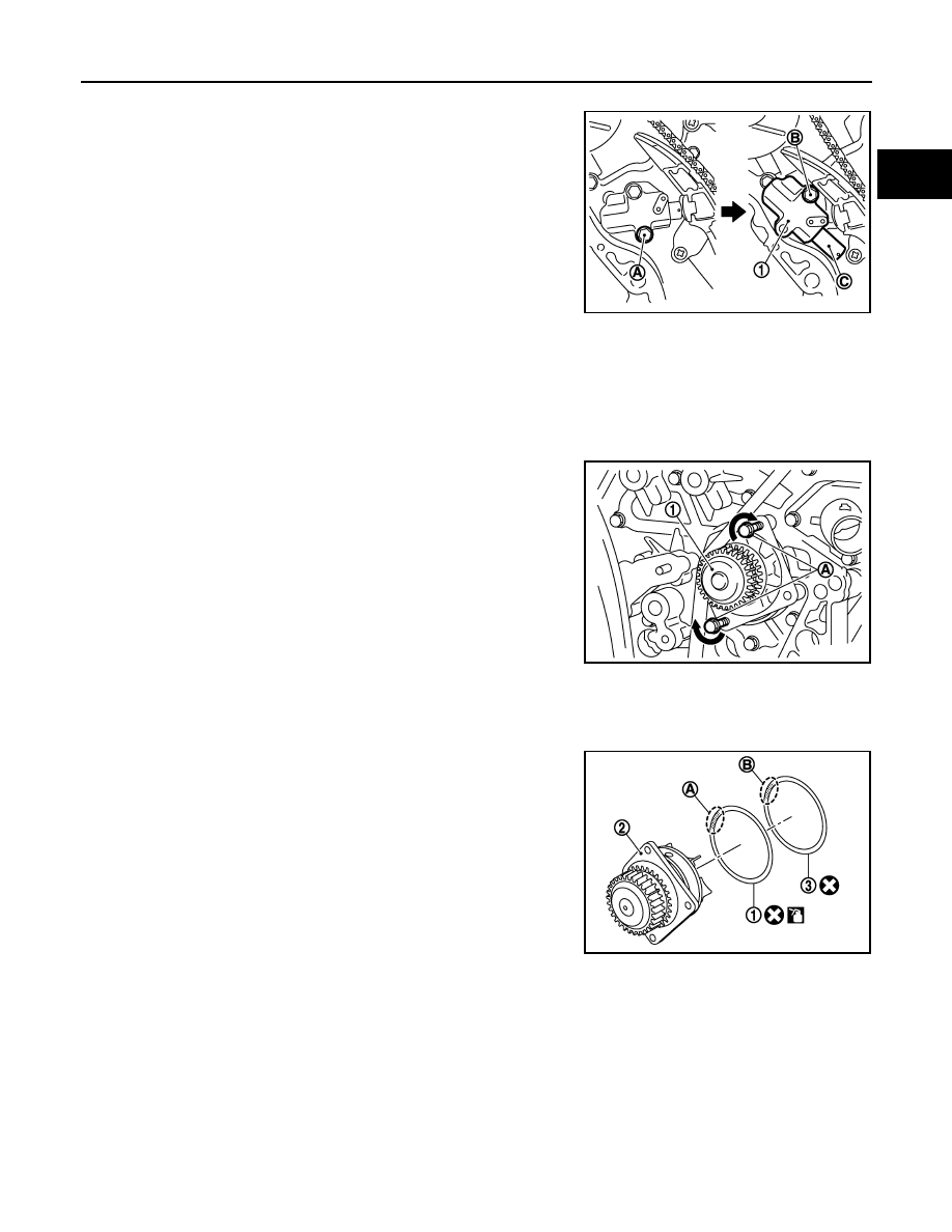
13. Remove timing chain tensioner (primary) as follows:
a.
Remove lower mounting bolt (A).
b.
Loosen upper mounting bolt (B) slowly, and then turn chain ten-
sioner (primary) (1) on the upper mounting bolt so that plunger
(C) is fully expanded.
NOTE:
Even if plunger is fully expanded, it is not dropped from the body
of timing chain tensioner (primary).
c.
Remove upper mounting bolt, and then remove timing chain tensioner (primary).
14. Remove water pump as follows:
a.
Remove three water pump mounting bolts. Secure a gap between water pump gear and timing chain, by
turning crankshaft counterclockwise until timing chain looseness on water pump sprocket becomes maxi-
mum.
b.
Screw M8 bolts (A) [pitch: 1.25 mm (0.0492 in) length: approxi-
mately 50 mm (1.97 in)] into water pumps upper and lower
mounting bolt holes until they reach timing chain case. Then,
alternately tighten each bolt for a half turn, and pull out water
pump (1).
CAUTION:
• Pull straight out while preventing vane from contacting
socket in installation area.
• Remove water pump without causing sprocket to contact
timing chain.
c.
Remove M8 bolts and O-rings from water pump.
CAUTION:
Never disassemble water pump.
INSTALLATION
1.
Install new O-rings to water pump.
• Apply engine oil to O-ring (1) and engine coolant to O-ring (3)
as shown in the figure.
• Locate O-ring with yellow paint mark (A) to front side.
• Locate O-ring with light blue paint mark (B) to rear side.
2.
Install water pump.
CAUTION:
Never allow cylinder block to nip O-rings when installing water pump.
• Check timing chain and water pump sprocket are engaged.
• Insert water pump by tightening mounting bolts alternately and evenly.
3.
Install timing chain tensioner (primary) as follows:
a.
Turn crankshaft clockwise so that timing chain on the timing chain tensioner (primary) side is loose.
JPBIA1537ZZ
JPBIA0111ZZ
2
: Water pump
JPBIA0112ZZ
CO-20
< ON-VEHICLE REPAIR >
WATER PUMP
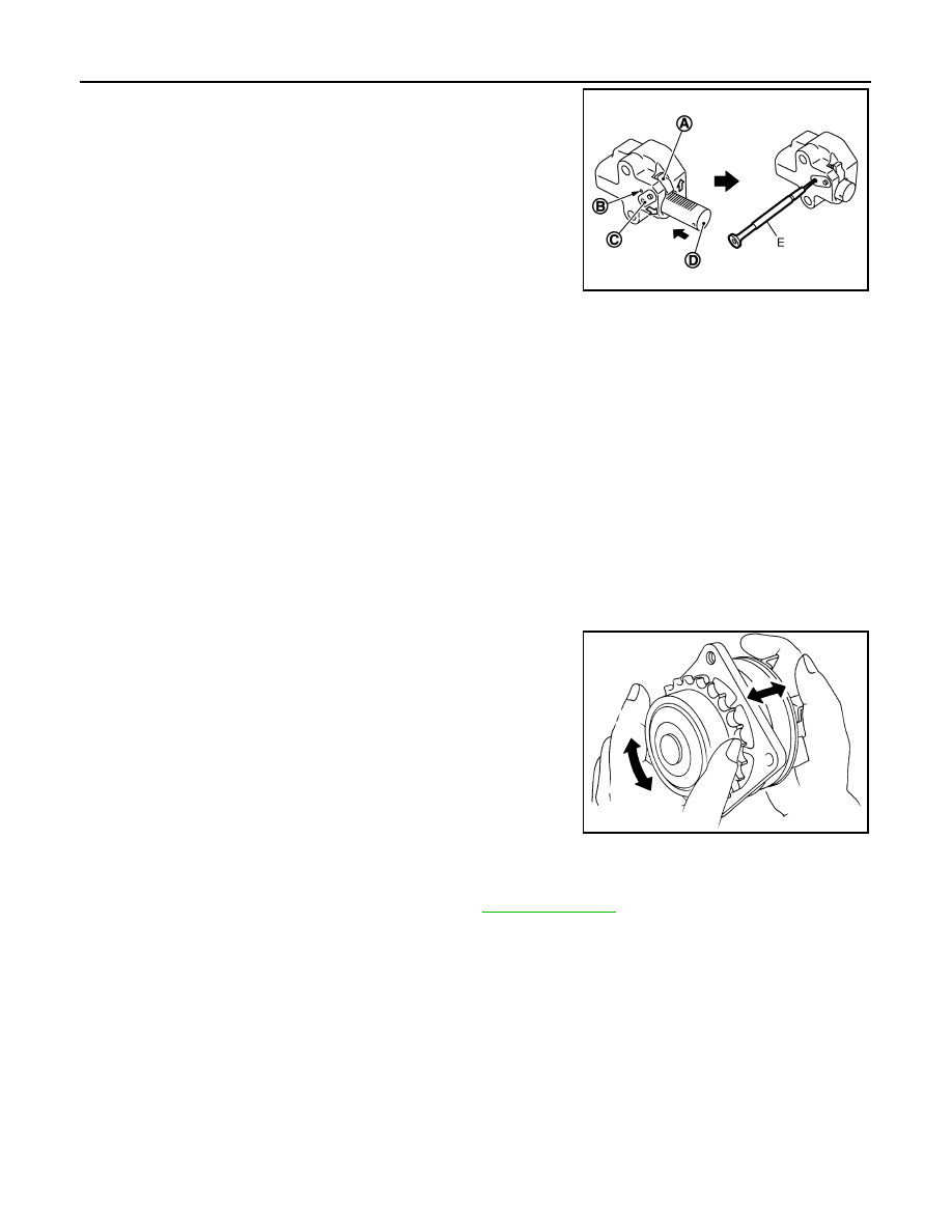
b.
Pull plunger stopper tab (A) up (or turn lever downward) so as to
remove plunger stopper tab from the ratchet of plunger (D).
NOTE:
Plunger stopper tab and lever (C) are synchronized.
c.
Push plunger into the inside of tensioner body.
d.
Hold plunger in the fully compressed position by engaging
plunger stopper tab with the tip of ratchet.
e.
To secure lever, insert stopper pin (E) through hole of lever into
tensioner body hole (B).
• The lever parts and the tab are synchronized. Therefore, the
plunger will be secured under this condition.
NOTE:
Figure shows the example of 1.2 mm (0.047 in) diameter thin screwdriver being used as the stopper pin.
f.
Install timing chain tensioner (primary).
• Remove dust and foreign material completely from backside of timing chain tensioner (primary) and
from installation area of rear timing chain case.
g.
Remove stopper pin.
h.
Check again that timing chain and water pump sprocket are engaged.
4.
Install in the reverse order of removal for remaining parts.
• After starting engine, let idle for three minutes, then rev engine up to 3,000 rpm under no load to
purge air from the high-pressure chamber of chain tensioner. Engine may produce a rattling
noise. This indicates that air still remains in the chamber and is not a matter of concern.
Inspection
INFOID:0000000003139296
INSPECTION AFTER REMOVAL
• Check for badly rusted or corroded water pump body assembly.
• Check for rough operation due to excessive end play.
• If anything is found, replace water pump.
INSPECTION AFTER INSTALLATION
• Check that the reservoir tank cap is tightened.
• Check for leakage of engine coolant using the radiator cap tester adapter (commercial service tool) and the
radiator cap tester (commercial service tool). Refer to
.
• Start and warm up the engine. Visually check that there is no leakage of engine coolant.
JPBIA0118ZZ
SLC943A
Нет комментариевНе стесняйтесь поделиться с нами вашим ценным мнением.
Текст