Infiniti EX35. Manual — part 203
AV
AV CONTROL UNIT
AV-593
< ECU DIAGNOSIS >
[BOSE AUDIO WITH NAVIGATION]
C
D
E
F
G
H
I
J
K
L
M
B
A
O
P
19
(Y)
Ground
Battery power supply
Input
Ignition
switch
OFF
—
Battery voltage
20
(B)
Ground
Ground
—
Ignition
switch
ON
—
0 V
21
(B)
Ground
Ground
—
Ignition
switch
ON
—
0 V
22
(Y)
Ground
Battery power supply
Input
Ignition
switch
OFF
—
Battery voltage
23
(B)
Ground
Ground
—
Ignition
switch
ON
—
0 V
24
(Y)
Ground
Battery power supply
Input
Ignition
switch
OFF
—
Battery voltage
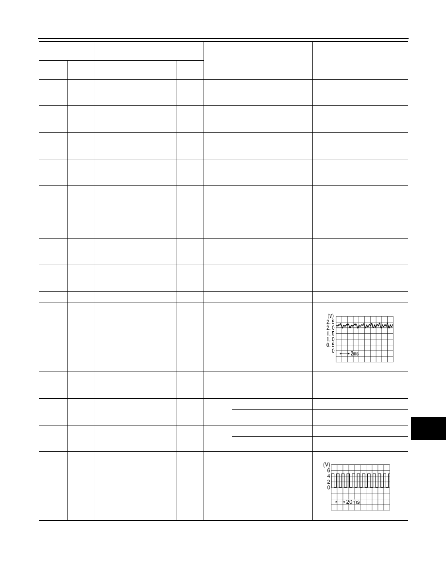
25
(V)
Ground
ACC power supply
Input
Ignition
switch
ACC
—
Battery voltage
26
(G)
27
Microphone VCC
Output
Ignition
switch
ON
—
5.0 V
27
Ground
Microphone ground
—
ON
—
0 V
28
(R)
27
Microphone signal
Input
Ignition
switch
ON
Give a voice
35
(G)
Ground
Ignition signal
Input
Ignition
switch
ON
—
Battery voltage
36
(V)
Ground
Parking brake signal
Input
Ignition
switch
ON
Parking brake ON
0 V
Parking brake OFF
12.0 V
37
(O)
Ground
Reverse signal
Input
Ignition
switch
ON
R position
12.0 V
Other than R position
0 V
38
(R)
Ground
Vehicle speed signal (8-
pulse)
Input
Ignition
switch
ON
When vehicle speed is ap-
prox. 40 km/h (25MPH)
Terminal
(Wire color)
Description
Condition
Reference value
(Approx.)
+
–
Signal name
Input/
Output
PKIB5037J
SKIA6649J
AV-594
< ECU DIAGNOSIS >
[BOSE AUDIO WITH NAVIGATION]
AV CONTROL UNIT
40
(W)
Ground
Camera-connection recog-
nition signal
Input
Ignition
switch
ON
Connected to camera con-
trol unit connector
0 V
Not connected to camera
control unit connector
5.0 V
41
(B)
Ground
Control signal 1
—
Ignition
switch
ON
—
0 V
42
(B)
Ground
Control signal 2
—
Ignition
switch
ON
—
0 V
43
(GR)
Ground
Control signal 3
—
Ignition
switch
ON
—
0 V
44
(SB)
Ground
Mode change signal
Output
Ignition
switch
ON
Driver's Audio Stage ON
0 V
Driver's Audio Stage OFF
8.5 V
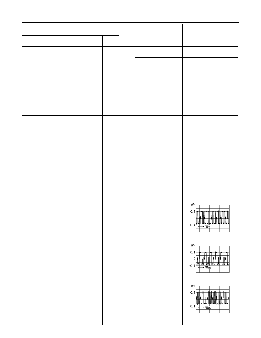
48
(G)
—
AV communication signal
(H)
Input/
Output
—
—
—
49
(R)
—
AV communication signal
(L)
Input/
Output
—
—
—
50
(LG)
—
AV communication signal
(H)
Input/
Output
—
—
—
51
(V)
—
AV communication signal
(L)
Input/
Output
—
—
—
52
(L)
—
CAN–H
Input/
Output
—
—
—
53
(P)
—
CAN–L
Input/
Output
—
—
—
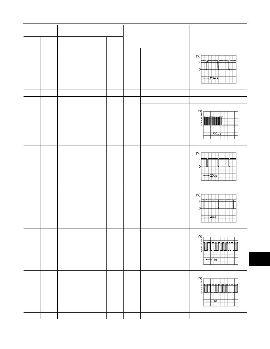
61
(B)
Ground
RGB signal (R: red)
Output
Ignition
switch
ON
Start confirmation/adjust-
ment mode, and then dis-
play color bar by selecting
“Color Spectrum Bar” on
DISPLAY DIAGNOSIS
screen.
62
(W)
Ground
RGB signal (G: green)
Output
Ignition
switch
ON
Start confirmation/adjust-
ment mode, and then dis-
play color bar by selecting
“Color Spectrum Bar” on
DISPLAY DIAGNOSIS
screen.
63
(R)
Ground
RGB signal (B: blue)
Output
Ignition
switch
ON
Start confirmation/adjust-
ment mode, and then dis-
play color bar by selecting
“Color Spectrum Bar” on
DISPLAY DIAGNOSIS
screen.
64
—
Shield
—
—
—
—
Terminal
(Wire color)
Description
Condition
Reference value
(Approx.)
+
–
Signal name
Input/
Output
SKIB2238J
SKIB2236J
SKIB2237J
AV
AV CONTROL UNIT
AV-595
< ECU DIAGNOSIS >
[BOSE AUDIO WITH NAVIGATION]
C
D
E
F
G
H
I
J
K
L
M
B
A
O
P
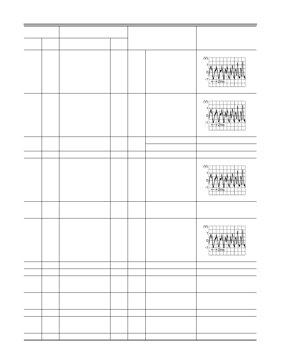
65
(G)
Ground
RGB synchronizing signal
Output
Ignition
switch
ON
—
66
—
Shield
—
—
—
—
67
(B)
Ground
RGB area (YS) signal
Output
Ignition
switch
ON
At RGB image display
5.0 V
At camera image or AUX
image display
68
(R)
Ground
Horizontal synchronizing
(HP) signal
Input
Ignition
switch
ON
—
69
(W)
Ground
Vertical synchronizing (VP)
signal
Input
Ignition
switch
ON
—
70
(BR)
Ground
Communication signal
(CONT
→
DISP)
Output
Ignition
switch
ON
When adjusting display
brightness.
71
(Y)
Ground
Communication signal
(DISP
→
CONT)
Input
Ignition
switch
ON
When adjusting display
brightness.
72
—
Shield
—
—
—
—
Terminal
(Wire color)
Description
Condition
Reference value
(Approx.)
+
–
Signal name
Input/
Output
SKIB3603E
PKIB4948J
SKIB3601E
SKIB3598E
PKIB5039J
PKIB5039J
AV-596
< ECU DIAGNOSIS >
[BOSE AUDIO WITH NAVIGATION]
AV CONTROL UNIT
WITHOUT REAR VIEW MONITOR AND AROUND VIEW MONITOR
79
(R)
95
(W)
iPod sound signal LH
Input
Ignition
switch
ON
When iPod mode is select-
ed
80
(B)
96
(G)
iPod sound signal RH
Input
Ignition
switch
ON
When iPod mode is select-
ed
85
(SB)
Ground
Eject signal
Input
—
Pressing the eject switch
0 V
Except for above
3.3 V
86
—
Shield
—
—
—
—
87
(R)
88
(W)
AUX sound signal LH
Input
Ignition
switch
ON
When AUX mode is select-
ed
102
(BR)
Ground
SW ground
—
Ignition
switch
ON
—
0 V
103
(B)
88
(B)
AUX sound signal RH
Input
Ignition
switch
ON
When AUX mode is select-
ed
105
—
FM sub
Input
—
—
—
106
—
AM–FM main
Input
—
—
—
107
Ground
Antenna amp. ON signal
Output
Ignition
switch
ACC
—
120. V
108
Ground
Satellite antenna signal
Input
Ignition
switch
ACC
Not connected to satellite
antenna connector
5.0 V
109
—
Shield
—
—
—
—
110
Ground
GPS antenna signal
Input
Ignition
switch
ACC
Not connected to GPS an-
tenna connector
5.0 V
111
—
Shield
—
—
—
—
Terminal
(Wire color)
Description
Condition
Reference value
(Approx.)
+
–
Signal name
Input/
Output
SKIB3609E
SKIB3609E
SKIB3609E
SKIB3609E
Нет комментариевНе стесняйтесь поделиться с нами вашим ценным мнением.
Текст