Infiniti EX35. Manual — part 1395

STC-6
< COMPONENT DIAGNOSIS >
[EPS]
POWER SUPPLY AND GROUND CIRCUIT
COMPONENT DIAGNOSIS
POWER SUPPLY AND GROUND CIRCUIT
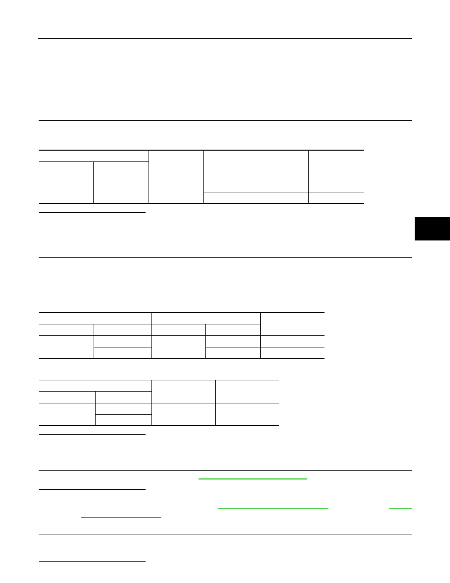
Description
INFOID:0000000003552473
Power supply to EPS system
Diagnosis Procedure
INFOID:0000000003552474
1.
CHECK POWER SUPPLY
1.
Turn the ignition switch OFF.
2.
Disconnect power steering control unit harness connector.
3.
Check voltage between power steering control unit harness connector and ground.
4.
Turn the ignition switch ON.
CAUTION:
Never start the engine.
5.
Check voltage between power steering control unit harness connector and ground.
Is the inspection result normal?
YES
>> GO TO 2.
NO
>>
Check the following. If any items are damaged, repair or replace damaged parts.
• 10A fuses (#45) open
- Harness for short or open between ignition switch and power steering control unit harness con-
nector No. 3 terminal.
- Ignition switch. Refer to
PCS-131, "Removal and Installation"
2.
CHECK GROUND CIRCUIT
1.
Turn the ignition switch OFF.
2.
Check continuity between power steering control unit harness connector and ground.
Is the inspection result normal?
YES
>> GO TO 3.
NO
>> Repair open circuit or short to power in harness or connectors.
3.
CHECK TERMINALS AND HARNESS CONNECTORS
Check power steering control unit pin terminals for damage or loose connection with harness connector.
Is the inspection result normal?
YES
>> INSPECTION END
NO
>> Repair or replace damaged parts.
Power steering control unit
—
Voltage
Connector
Terminal
M108
3 Ground
0
V
Power steering control unit
—
Voltage
Connector
Terminal
M108
3 Ground
Battery
voltage
Power steering control unit
—
Continuity
Connector
Terminal
M108
6 Ground
Existed
POWER STEERING SOLENOID VALVE
STC-7
< COMPONENT DIAGNOSIS >
[EPS]
C
D
E
F
H
I
J
K
L
M
A
B
STC
N
O
P
POWER STEERING SOLENOID VALVE
Description
INFOID:0000000003552475
Power steering solenoid valve controls the power steering oil pressure in the gear housing assembly.
Diagnosis Procedure
INFOID:0000000003552476
1.
CHECK POWER STEERING SOLENOID VALVE SIGNAL
1.
Turn the ignition switch OFF.
2.
Check voltage between power steering control unit harness connector and ground.
Is the inspection result normal?
YES
>> GO TO 2.
NO
>> GO TO 4.
2.
CHECK HARNESS BETWEEN POWER STEERING SOLENOID VALVE AND POWER STEERING CON-
TROL UNIT
1.
Turn the ignition switch OFF.
2.
Disconnect power steering solenoid valve harness connector.
3.
Disconnect power steering control unit harness connector.
4.
Check the continuity between power steering solenoid valve harness connector and the power steering
control unit harness connector.
5.
Check continuity between power steering control unit harness connector and ground.
Is the inspection result normal?
YES
>> GO TO 3.
NO
>> Repair or replace damaged parts.
3.
CHECK POWER STEERING SOLENOID VALVE
Check power steering solenoid valve. Refer to
.
Is the inspection result normal?
YES
>> GO TO 4.
NO
>> Replace gear-sub assembly. Refer to
(2WD models),
(AWD models).
4.
CHECK TERMINALS AND HARNESS CONNECTORS
• Check power steering control unit pin terminals for damage or loose connection with harness connector.
• Check power steering solenoid valve pin terminals for damage or loose connection with harness connector.
Is the inspection result normal?
Power steering control unit
—
Condition
Voltage (Approx.)
Connector
Terminal
M108
1
Ground
Vehicle speed: 0 km/h (0 MPH)
(Engine is running)
4.4 – 6.6 V
Vehicle speed: 100 km/h (62 MPH)
2.4 – 3.6 V
Power steering solenoid valve
Power steering control unit
Continuity
Connector
Terminal
Connector
Terminal
F45
1
M108
1
Existed
2
5
Existed
Power steering control unit
—
Continuity
Connector
Terminal
M108
1
Ground
Not existed
5

STC-8
< COMPONENT DIAGNOSIS >
[EPS]
POWER STEERING SOLENOID VALVE
YES
>> INSPECTION END
NO
>> Repair or replace damaged parts.
Component Inspection
INFOID:0000000003552477
1.
CHECK POWER STEERING SOLENOID VALVE
1.
Turn the ignition switch OFF.
2.
Disconnect power steering solenoid valve harness connector.
3.
Check resistance between power steering solenoid valve connector terminals.
4.
Check power steering solenoid valve by listening for its operation sound while applying battery voltage to
power steering solenoid valve connector F45 terminals 1 (positive) and 2 (negative).
Is the inspection result normal?
YES
>> INSPECTION END
NO
>> Replace gear-sub assembly. Refer to
(2WD models),
(AWD models).
Power steering solenoid valve
Resistance (Approx.)
Connector
Terminal
F45
1 2
4
–
6
Ω

ENGINE SPEED SIGNAL CIRCUIT
STC-9
< COMPONENT DIAGNOSIS >
[EPS]
C
D
E
F
H
I
J
K
L
M
A
B
STC
N
O
P
ENGINE SPEED SIGNAL CIRCUIT
Description
INFOID:0000000003552478
ECM sends engine speed signal to power steering control unit.
Diagnosis Procedure
INFOID:0000000003552479
1.
PERFORM ECM SELF-DIAGNOSIS
With CONSULT-III
1.
Turn the ignition switch ON.
Perform ECM self-diagnosis. Refer to
EC-113, "CONSULT-III Function"
.
Is any DTC detected?
YES
>> Check the DTC.
NO
>> GO TO 2.
2.
CHECK HARNESS BETWEEN ECM AND POWER STEERING CONTROL UNIT
1.
Turn the ignition switch OFF.
2.
Disconnect ECM harness connectors.
3.
Disconnect power steering control unit harness connector.
4.
Check continuity between ECM harness connector and power steering control unit harness connector.
5.
Check continuity between power steering control unit harness connector and ground.
Is the inspection result normal?
YES
>> GO TO 3.
NO
>> Repair or replace damaged parts.
3.
CHECK ENGINE SPEED SIGNAL (1)
1.
Connect ECM harness connectors.
2.
Check signal between ECM harness connector and ground with oscilloscope.
ECM
Power steering control unit
Continuity
Connector
Terminal
Connector
Terminal
M107
110
M108
10
Existed
Power steering control unit
—
Continuity
Connector
Terminal
M108
10
Ground
Not existed
Нет комментариевНе стесняйтесь поделиться с нами вашим ценным мнением.
Текст