Infiniti EX35. Manual — part 1396
STC-10
< COMPONENT DIAGNOSIS >
[EPS]
ENGINE SPEED SIGNAL CIRCUIT
Is the inspection result normal?
YES
>> GO TO 4.
NO
>> Replace ECM. Refer to
EC-15, "ADDITIONAL SERVICE WHEN REPLACING CONTROL UNIT :
.
4.
CHECK ENGINE SPEED SIGNAL (2)
1.
Turn the ignition switch OFF.
2.
Connect power steering control unit harness connector.
3.
Check signal between power steering control unit harness connector and ground with oscilloscope.
Is the inspection result normal?
YES
>> GO TO 5.
NO
>> Replace power steering control unit. Refer to
5.
CHECK TERMINALS AND HARNESS CONNECTORS
• Check power steering control unit pin terminals for damage or loose connection with harness connector.
• Check ECM pin terminals for damage or loose connection with harness connector.
Is the inspection result normal?
YES
>> INSPECTION END
NO
>> Repair or replace damaged parts.
ECM
—
Condition
Voltage (Approx.)
Connector
Terminal
M107
110
Ground
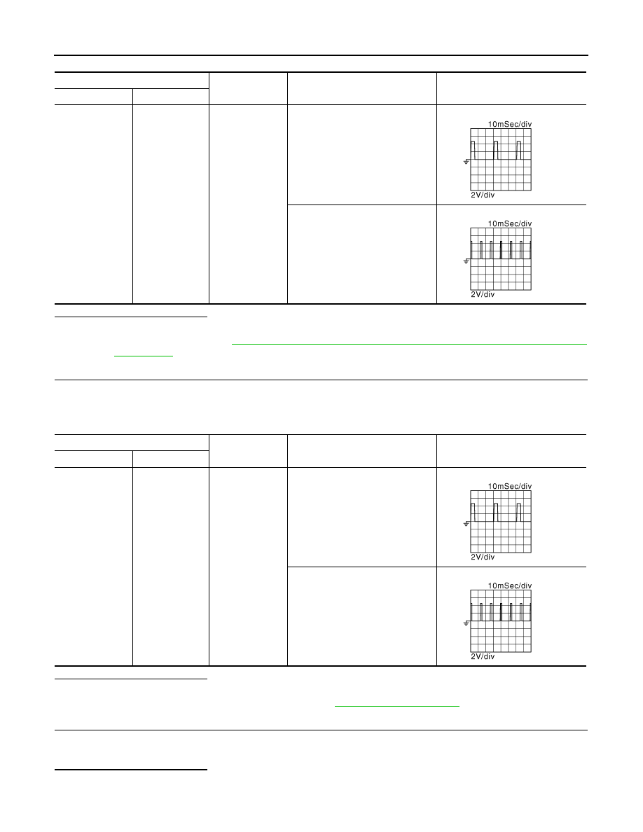
Engine is running
• Warm-up condition
• Idle speed
Engine is running
• Warm-up condition
• Engine speed: Approx. 2,000 rpm
JMBIA0076GB
JMBIA0077GB
Power steering control unit
—
Condition
Voltage (Approx.)
Connector
Terminal
M108
10
Ground
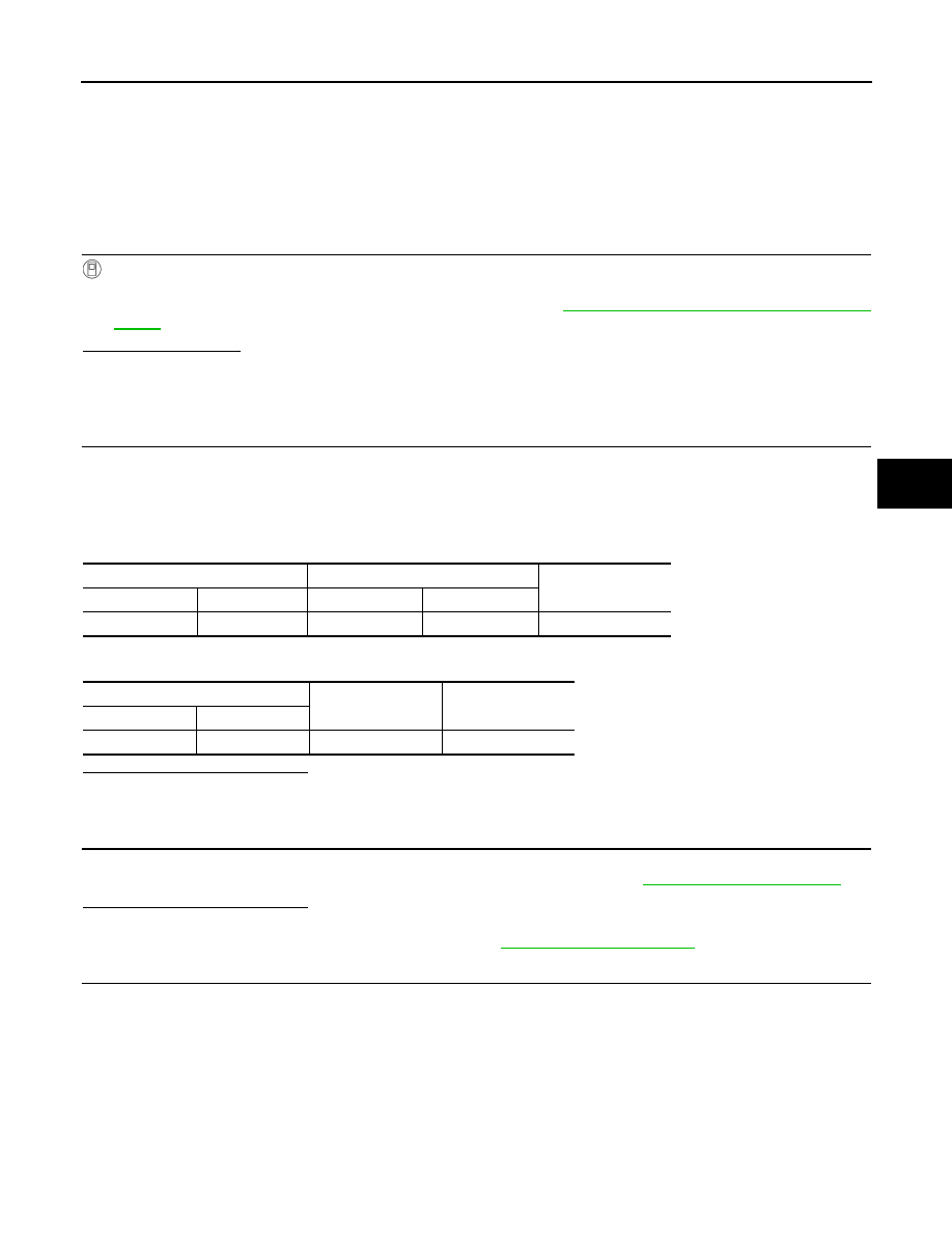
Engine is running
• Warm-up condition
• Idle speed
Engine is running
• Warm-up condition
• Engine speed: Approx. 2,000 rpm
JMBIA0076GB
JMBIA0077GB
VEHICLE SPEED SIGNAL CIRCUIT
STC-11
< COMPONENT DIAGNOSIS >
[EPS]
C
D
E
F
H
I
J
K
L
M
A
B
STC
N
O
P
VEHICLE SPEED SIGNAL CIRCUIT
Description
INFOID:0000000003552480
Unified meter and A/C amp. sends vehicle speed signal to power steering control unit.
Diagnosis Procedure
INFOID:0000000003552481
1.
PERFORM UNIFIED METER AND A/C AMP. SELF-DIAGNOSIS
With CONSULT-III
1.
Turn the ignition switch ON.
2.
Perform unified meter and A/C amp. self-diagnosis. Refer to
MWI-40, "CONSULT-III Function (METER/
Is any DTC detected?
YES
>> Check the DTC.
NO
>> GO TO 2.
2.
CHECK HARNESS BETWEEN UNIFIED METER AND A/C AMP. AND POWER STEERING CONTROL
UNIT
1.
Turn the ignition switch OFF.
2.
Disconnect unified meter and A/C amp. harness connector.
3.
Disconnect power steering control unit harness connector.
4.
Check continuity between unified meter and A/C amp. harness connector and power steering control unit
harness connector.
5.
Check continuity between power steering control unit harness connector and ground.
Is the inspection result normal?
YES
>> GO TO 3.
NO
>> Repair or replace damaged parts.
3.
CHECK VEHICLE SPEED SIGNAL (1)
1.
Connect unified meter and A/C amp. harness connector.
2.
Check unified meter and A/C amp. input/output standard values. Refer to
Is the inspection result normal?
YES
>> GO TO 4.
NO
>> Replace unified meter and A/C amp. Refer to
4.
CHECK VEHICLE SPEED SIGNAL (2)
1.
Turn the ignition switch OFF.
2.
Connect power steering control unit harness connector.
3.
Check signal between power steering control unit harness connector and ground with oscilloscope.
Unified meter and A/C amp.
Power steering control unit
Continuity
Connector
Terminal
Connector
Terminal
M66
8
M108
8
Existed
Power steering control unit
—
Continuity
Connector
Terminal
M108
8
Ground
Not existed
STC-12
< COMPONENT DIAGNOSIS >
[EPS]
VEHICLE SPEED SIGNAL CIRCUIT
Is the inspection result normal?
YES
>> GO TO 5.
NO
>> Replace power steering control unit. Refer to
5.
CHECK TERMINALS AND HARNESS CONNECTORS
• Check power steering control unit pin terminals for damage or loose connection with harness connector.
• Check unified meter and A/C amp. pin terminals for damage or loose connection with harness connector.
Is the inspection result normal?
YES
>> INSPECTION END
NO
>> Repair or replace damaged parts.
Power steering control unit
—
Condition
Voltage (Approx.)
Connector
Terminal
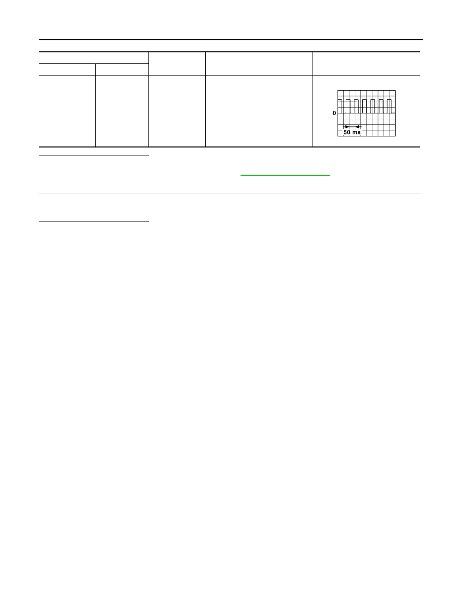
M108
8
Ground
Vehicle speed: 40 km/h (25 MPH)
CAUTION:
Check air pressure of tire under
standard condition.
JSNIA0015GB
POWER STEERING CONTROL UNIT
STC-13
< ECU DIAGNOSIS >
[EPS]
C
D
E
F
H
I
J
K
L
M
A
B
STC
N
O
P
ECU DIAGNOSIS
POWER STEERING CONTROL UNIT
Reference Value
INFOID:0000000003552482
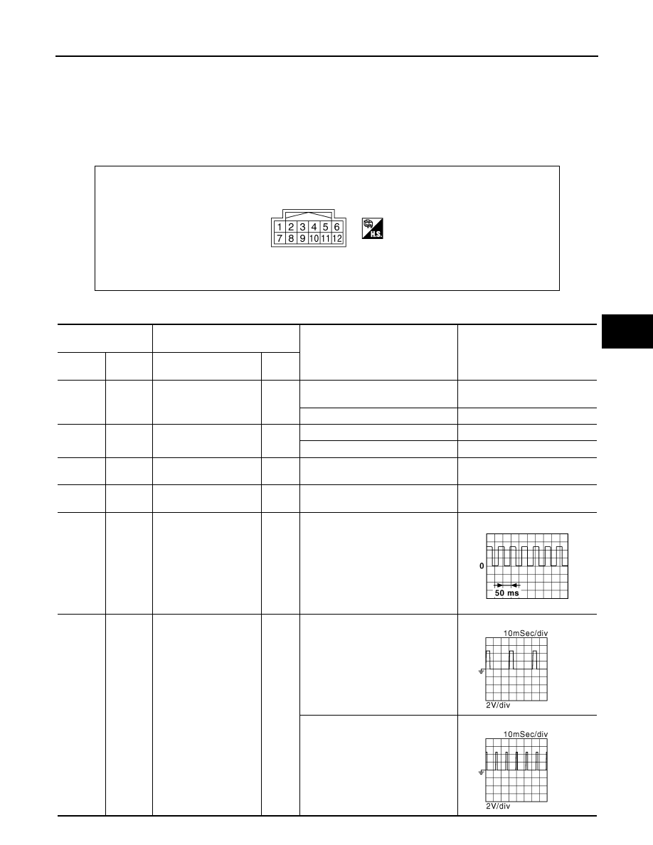
TERMINAL LAYOUT
PHYSICAL VALUES
JSGIA0023ZZ
Terminal No.
(Wire color)
Description
Condition
Value (Approx.)
+
-
Signal name
Input/
Output
1
(LG)
Ground
Power steering solenoid
valve voltage
Output
Vehicle speed: 0 km/h (0 MPH)
(Engine is running)
4.4 – 6.6 V
Vehicle speed: 100 km/h (62 MPH)
2.4 – 3.6 V
3
(G)
Ground
Ignition switch power
supply
Input
Ignition switch: ON
Battery voltage
Ignition switch: OFF
0 V
5
(B)
Ground
Power steering solenoid
valve ground
—
Always
0 V
6
(B)
Ground
Ground
—
Always
0 V
8
(L)
Ground
Vehicle speed signal
Input
Vehicle speed: 40 km/h (25 MPH)
CAUTION:
Check air pressure of tire under
standard condition.
10
(R)
Ground
Engine speed signal
Input
Engine is running
• Warm-up condition
• Idle speed
Engine is running
• Warm-up condition
• Engine speed: Approx. 2,000 rpm
JSNIA0015GB
JMBIA0076GB
JMBIA0077GB
Нет комментариевНе стесняйтесь поделиться с нами вашим ценным мнением.
Текст