Infiniti EX35. Manual — part 371
CCS
INTELLIGENT CRUISE CONTROL SYSTEM
CCS-19
< FUNCTION DIAGNOSIS >
[INTELLIGENT CRUISE CONTROL]
C
D
E
F
G
H
I
J
K
L
M
B
N
P
A
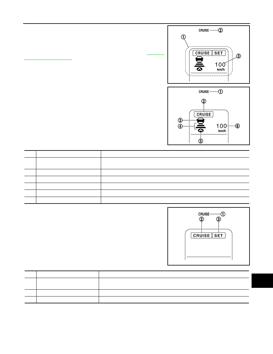
The multi information display (1) and ICC system warning lamp (2) in
the combination meter indicate the operation status of the ICC sys-
tem.
NOTE:
When the on board self-diagnosis is run, ICC system DTC (s), if any,
are displayed in the set vehicle speed indicator (3). Refer to
.
In Vehicle-To-Vehicle Distance Control Mode
In Conventional (Fixed Speed) Cruise Control Mode
ICC SENSOR INTEGRATED UNIT INPUT/OUTPUT SIGNAL ITEM
Input Signal Items
JSOIA0020ZZ
JSOIA0011ZZ
No.
Display items
Description
1
ICC system warning lamp
(CRUISE warning lamp)
This indicates that an abnormal condition is present in the ICC system.
2
MAIN switch indicator
Indicates that the MAIN switch is ON (ICC system ON).
3
Vehicle ahead detection indicator
Indicates whether it detects a vehicle ahead.
4
Set distance indicator
Indicates the selected distance between vehicles set with the DISTANCE switch.
5
Own vehicle indicator
Indicates the base vehicle.
6
Set vehicle speed indicator
Indicates the set vehicle speed.
JSOIA0012ZZ
No.
Display items
Description
1
ICC system warning lamp
(CRUISE warning lamp)
This indicates that an abnormal condition is present in the ICC system.
2
MAIN switch indicator
Indicates that the MAIN switch is ON (ICC system ON).
3
SET switch indicator
Indicates that the set conventional (fixed speed) cruise control mode is controlled.

CCS-20
< FUNCTION DIAGNOSIS >
[INTELLIGENT CRUISE CONTROL]
INTELLIGENT CRUISE CONTROL SYSTEM
Output Signal Items
Transmission unit
Signal name
Description
ECM
Accelerator pedal position signal
ICC sensor integrated unit receives accelerator pedal position signal
from ECM with CAN communication.
ICC steering
switch signal
MAIN switch signal
ICC sensor integrated unit receives ICC steering switch signal from
ECM with CAN communication.
SET/COAST switch
signal
CANCEL switch sig-
nal
RESUME/ACCEL-
ERATE switch signal
DISTANCE switch
signal
ICC brake switch signal
ICC sensor integrated unit receives ICC brake switch signal from
ECM with CAN communication.
Stop lamp switch signal
ICC sensor integrated unit receives stop lamp switch signal from
ECM with CAN communication.
Closed throttle position signal
ICC sensor integrated unit receives closed throttle position signal
from ECM with CAN communication.
Engine speed signal
ICC sensor integrated unit receives engine speed signal from ECM
with CAN communication.
TCM
Shift position signal
ICC sensor integrated unit receives shift position signal from TCM
with CAN communication.
Output shaft revolution signal
ICC sensor integrated unit receives A/T vehicle speed sensor signal
(output shaft revolution signal) from TCM with CAN communication.
Current gear position signal
ICC sensor integrated unit receives current gear position signal from
TCM with CAN communication.
ABS actuator and
electric unit (con-
trol unit)
Vehicle speed signal
ICC sensor integrated unit receives vehicle speed signal (wheel
speed) from ABS actuator and electric unit (control unit) with CAN
communication.
BCM
Front wiper request signal
ICC sensor integrated unit receives front wiper request signal from
BCM with CAN communication.
Reception unit
Signal name
Description
Combination
meter (through
unified meter and
A/C amp.)
Meter display sig-
nal
CRUISE indicator
signal
ICC sensor integrated unit transmits meter display signal to combi-
nation meter (through unified meter and A/C amp.) with CAN com-
munication.
Own vehicle indica-
tor signal
Vehicle ahead de-
tection indicator sig-
nal
SET indicator signal
Set distance indica-
tor signal
ICC system warning lamp signal
ICC sensor integrated unit transmits ICC system warning lamp sig-
nal to combination meter (through unified meter and A/C amp.) with
CAN communication.
Buzzer output signal
ICC sensor integrated unit transmits buzzer output signal to combi-
nation meter (through unified meter and A/C amp.) with CAN com-
munication.
ICC brake hold re-
lay
ICC brake hold relay drive signal
ICC sensor integrated unit output stop lamp drive signal to ICC
brake hold relay.
CCS
INTELLIGENT CRUISE CONTROL SYSTEM
CCS-21
< FUNCTION DIAGNOSIS >
[INTELLIGENT CRUISE CONTROL]
C
D
E
F
G
H
I
J
K
L
M
B
N
P
A
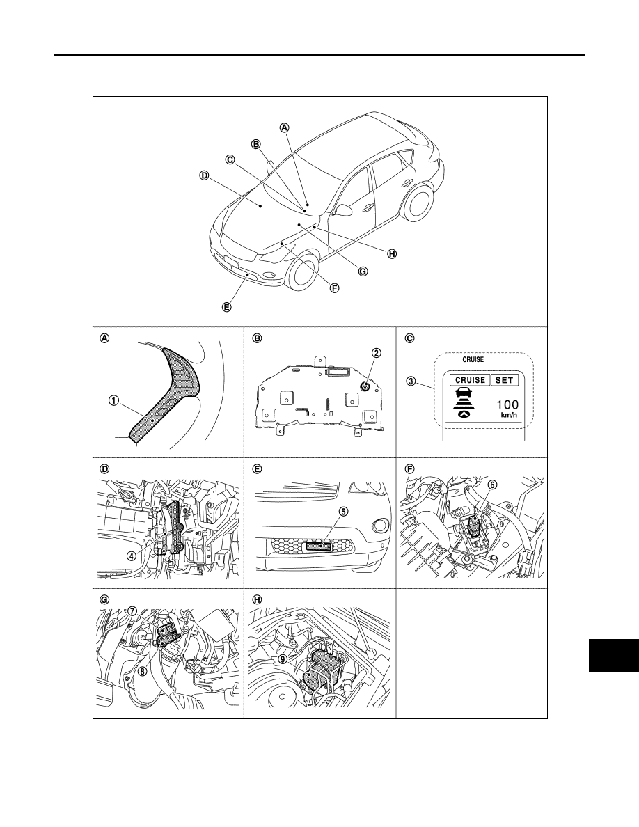
Component Parts Location
INFOID:0000000003130030
1.
ICC steering switch
2.
Buzzer
3.
ICC system display, ICC warning
lamp
4.
ECM
5.
ICC sensor integrated unit
6.
ICC brake hold relay
7.
ICC brake switch
8.
Stop lamp switch
9.
ABS actuator and electric unit (con-
trol unit)
JPOIA0119ZZ
CCS-22
< FUNCTION DIAGNOSIS >
[INTELLIGENT CRUISE CONTROL]
INTELLIGENT CRUISE CONTROL SYSTEM
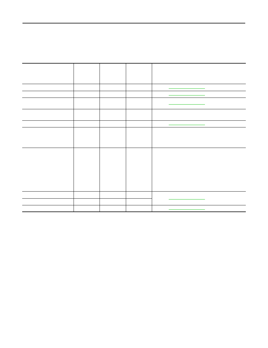
Component Description
INFOID:0000000003130031
×
: Applicable
A.
Steering wheel RH
B.
Back of combination meter
C.
In combination meter
D.
Behind the glove box
E.
Front bumper LH
F.
Engine room LH
G.
Brake pedal
H.
Inside brake master cylinder cover
Component
Vehicle-to-
vehicle
distance
control mode
Conventional
(Fixed speed)
cruise
control mode
Brake assist
(With preview
function)
Description
ICC sensor integrated unit
×
×
×
Refer to
.
ECM
×
×
×
Refer to
.
ABS actuator and electric
unit (control unit)
×
×
×
Refer to
.
BCM
×
Transmits front wiper request signal to ICC sensor inte-
grated unit through CAN communication.
TCM
×
×
Refer to
.
Unified meter and A/C amp.
×
×
×
Receives the meter display signal, ICC warning lamp
signal and buzzer output signal from the ICC sensor in-
tegrated unit with CAN communication. Transmits the
data to the combination meter with communication line.
Combination meter
×
×
×
Using the signals received from the unified meter A/C
amp. with communication line, performs the following
operations.
• Displays the ICC system operation status according
to the meter display signal.
• Illuminates the ICC warning lamp according to the
ICC warning lamp signal.
• Operates the buzzer according to the buzzer output
signal.
ICC brake switch
×
×
×
Refer to
.
Stop lamp switch
×
×
×
ICC brake hold relay
×
×
×
Refer to
.
Нет комментариевНе стесняйтесь поделиться с нами вашим ценным мнением.
Текст