Infiniti EX35. Manual — part 372
CCS
DIAGNOSIS SYSTEM (ICC SENSOR INTEGRATED UNIT)
CCS-23
< FUNCTION DIAGNOSIS >
[INTELLIGENT CRUISE CONTROL]
C
D
E
F
G
H
I
J
K
L
M
B
N
P
A
DIAGNOSIS SYSTEM (ICC SENSOR INTEGRATED UNIT)
Diagnosis Description
INFOID:0000000003130032
The ICC system includes the on board self-diagnosis function that allows the technician to check for any trou-
ble codes on the ICC system display by operating the ICC steering switch.
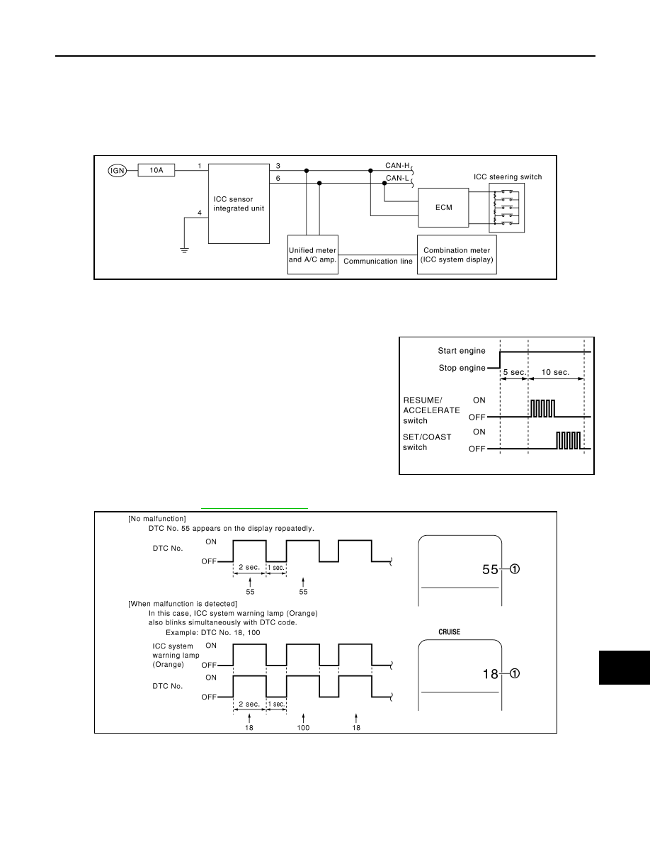
ON BOARD SELF-DIAGNOSIS SYSTEM DIAGRAM
ON BOARD SELF-DIAGNOSIS OPERATION PROCEDURE
1.
Turn ignition switch OFF.
2.
Start engine.
3.
Wait 5 seconds after starting engine, then within 10 seconds,
push up RESUME/ACCELERATE switch 5 times, and push
down SET/COAST switch 5 times.
NOTE:
• Never turn the MAIN switch ON.
• When operation above is not completed within the specified
period, go back to procedure 1 and do all over again.
4.
When the on board self-diagnosis starts up, the ICC system display shows DTC No. (1) at the set vehicle
speed indicator. Refer to
.
NOTE:
• DTC will disappear after 5 minutes.
• When more than one malfunction is detected, a maximum of 3 code numbers can be stored; the latest
malfunction will be displayed first.
WHEN ON BOARD SELF-DIAGNOSIS WILL NOT START UP
JSOIA0009GB
PKIB8371E
JSOIA0008GB
CCS-24
< FUNCTION DIAGNOSIS >
[INTELLIGENT CRUISE CONTROL]
DIAGNOSIS SYSTEM (ICC SENSOR INTEGRATED UNIT)
If the on board self-diagnosis does not start up, check the following items.
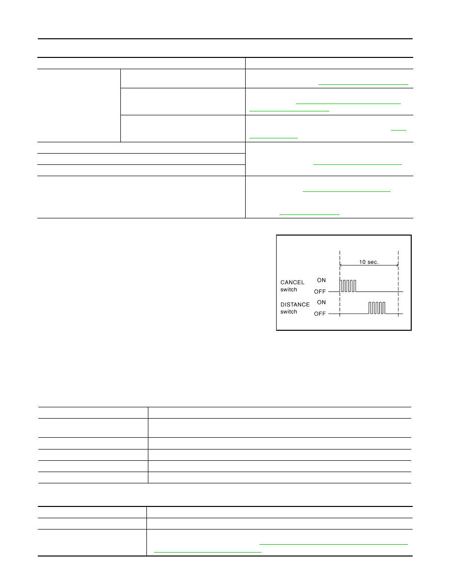
ERASING ON BOARD SELF-DIAGNOSIS
1.
Stop the vehicle and turn ignition switch OFF.
2.
Start engine and start on board self-diagnosis.
3.
During on board self-diagnosis, press CANCEL switch 5 times,
and DISTANCE switch 5 times in this order.
NOTE:
• Press them within 10 seconds after pressing CANCEL switch
at first.
• When operation is not completed within 10 seconds, start
again from step 2 above.
4.
DTC 55 will be shown.
NOTE:
DTC of an existing malfunction will not be erased.
5.
Turn ignition switch OFF to exit the diagnosis.
CONSULT-III Function (ICC)
INFOID:0000000003130033
DESCRIPTION
CONSULT-III can display each diagnostic item using the diagnostic test modes shown following.
WORK SUPPORT
Assumed abnormal point
Inspection item
Combination meter system.
Combination meter malfunction.
Check that the self-diagnosis function of the combination
meter starts up. Refer to
MWI-38, "Diagnosis Description"
.
Unified meter and A/C amp. malfunction.
Inspect the unified meter and A/C amp. power and ground
circuits. Refer to
MWI-53, "UNIFIED METER AND A/C
.
Communication error of the combination
meter and the unified meter and A/C amp.
Start up the self-diagnosis of the unified meter and A/C
amp. and check the self-diagnosis results. Refer to
ICC steering switch malfunction.
Perform the inspection for DTC “C1A06: OPERATION SW
CIR” (DTC 6). Refer to
Harness malfunction between ICC steering switch and ECM.
ECM malfunction.
ICC sensor integrated unit malfunction.
• Inspect the ICC sensor integrated unit power and ground
circuits. Refer to
• Perform the self-diagnosis for the ICC sensor integrated
unit with CONSULT-III, and check the diagnosis results.
Refer to
.
PKIB8373E
Test mode
Function
Work Support
• Monitors aiming direction to facilitate laser beam aiming operation.
• Indicates causes of automatic cancellation of the ICC system.
Self Diagnostic Result
Displays malfunctioning system memorized in ICC sensor integrated unit.
Data Monitor
Displays real-time input/output data of ICC sensor integrated unit.
Active Test
Enables operation check of electrical loads by sending driving signal to them.
ECU Identification
Displays part number of ICC sensor integrated unit.
Work support item
Function
CAUSE OF AUTO-CANCEL
Indicates causes of automatic cancellation of the ICC system.
LASER BEAM ADJUST
Outputs laser beam, calculates dislocation of the beam, and indicates adjustment direction.
For the adjustment procedure, refer to
CCS-8, "LASER BEAM AIMING ADJUSTMENT : Spe-

CCS
DIAGNOSIS SYSTEM (ICC SENSOR INTEGRATED UNIT)
CCS-25
< FUNCTION DIAGNOSIS >
[INTELLIGENT CRUISE CONTROL]
C
D
E
F
G
H
I
J
K
L
M
B
N
P
A
Cause of Auto-Cancel Display Item List
×
: Applicable
• Last five cancel (system cancel) causes are displayed.
• “CAUSE OF AUTO-CANCEL” displays times of ignition switch ON/OFF up to 254 maximum. 254 is kept
though the number exceeds 254. The number returns to 0 when detecting the same cancellation causes.
SELF DIAGNOSTIC RESULT
For details, refer to
NOTE:
“DTC RESULTS” and “TIME” are indicated on “Self Diagnostic Result”. “TIME” is used as a reference data of
diagnosis. It shows when malfunction is detected.
“TIME” shows the following.
• 0: malfunction is detected at present (from malfunction detection to ignition switch OFF).
CAN communication (U1000, U1010)
• 1 ~ 39: Displays when it is normal at present and finds malfunction in the past. It increases like
0
→
1
→
2...38
→
39 after returning to the normal condition whenever IGN OFF
→
ON. If it is over 39, it is fixed to
39 until the self-diagnostic results are erased. It returns to 0 when malfunction is detected again in the pro-
cess.
Other than CAN communication (other than U1000, U1010)
• 1 ~ 49: Displays when it is normal at present and finds malfunction in the past. It increases like
0
→
1
→
2...48
→
49 after returning to the normal condition whenever IGN OFF
→
ON. If it is over 49, it is fixed to
49 until the self-diagnostic results are erased. It returns to 0 when malfunction is detected again in the pro-
cess.
Cause of cancellation
Vehicle-to-vehi-
cle distance
control mode
Conventional
(fixed speed)
cruise control
mode
Description
OPERATING WIPER
×
Windshield wipers were operated at HI or LO speed operation.
OPERATING ABS
×
ABS function was operated.
OPERATING TCS
×
×
TCS function was operated.
OPERATING VDC
×
×
VDC function was operated.
OPE SW VOLT CIRC
×
×
The ICC steering switch input voltage is not within standard range.
ECM CIRCUIT
×
×
ECM did not permit ICC operation.
LASER SUN BEAM
×
Intense light such as sunlight entered ICC sensor integrated unit
light sensing part.
LASER TEMP
×
Temperature around ICC sensor integrated unit became low.
OP SW DOUBLE TOUCH
×
×
ICC steering switches were pressed at the same time.
WHL SPD ELEC NOISE
×
×
Wheel speed sensor signal caught electromagnetic noise.
VDC/TCS OFF SW
×
VDC OFF switch was pressed.
WHEEL SPD UNMATCH
×
×
Wheel speed became different from A/T vehicle speed.
TIRE SLIP
×
×
Wheel slipped.
IGN LOW VOLT
×
×
Power supply voltage became low.
SNOW MODE SW
×
Snow mode switch was pressed.
VHCL SPD DOWN
×
×
Vehicle speed becomes 32 km/h (20 MPH) and under.
VHCL SPD UNMATCH
×
×
Vehicle speed becomes unusual.
CAN COMM ERROR
×
×
ICC sensor integrated unit received an abnormal signal with CAN
communication.
ABS/TCS/VDC CIRC
×
×
An abnormal condition occurs in ABC/TCS/VDC system.
ECD CIRCUIT
×
An abnormal condition occurs in ECD system.
ASCD VHCL SPD DTAC
×
Vehicle speed is detached from set vehicle speed.
ASCD DOUBLE COMD
×
Cancel switch and operation switch are detected simultaneously.
NO RECORD
×
×
—

CCS-26
< FUNCTION DIAGNOSIS >
[INTELLIGENT CRUISE CONTROL]
DIAGNOSIS SYSTEM (ICC SENSOR INTEGRATED UNIT)
DATA MONITOR
×
: Applicable
Monitored Item [unit]
MAIN
SIGNALS
Description
MAIN SW
[On/Off]
×
Indicates [On/Off] status as judged from ICC steering switch signal (ECM transmits ICC steer-
ing switch signal through CAN communication).
SET/COAST SW
[On/Off]
×
Indicates [On/Off] status as judged from ICC steering switch signal (ECM transmits ICC steer-
ing switch signal through CAN communication).
CANCEL SW
[On/Off]
×
Indicates [On/Off] status as judged from ICC steering switch signal (ECM transmits ICC steer-
ing switch signal through CAN communication).
RESUME/ACC SW
[On/Off]
×
Indicates [On/Off] status as judged from ICC steering switch signal (ECM transmits ICC steer-
ing switch signal through CAN communication).
DISTANCE SW
[On/Off]
Indicates [On/Off] status as judged from ICC steering switch signal (ECM transmits ICC steer-
ing switch signal through CAN communication).
CRUISE OPE
[On/Off]
×
Indicates whether controlling or not (ON means “controlling”).
BRAKE SW
[On/Off]
×
Indicates [On/Off] status as judged from ICC brake switch signal (ECM transmits ICC brake
switch signal through CAN communication).
STOP LAMP SW
[On/Off]
×
Indicates [On/Off] status as judged from stop lamp switch signal (ECM transmits stop lamp
switch signal through CAN communication).
IDLE SW
[On/Off]
Indicates [On/Off] status of idle switch read from ICC sensor integrated unit through CAN
communication (ECM transmits On/Off status through CAN communication).
SET DISTANCE
[Shor/Mid/Long]
×
Indicates set distance memorized in ICC sensor integrated unit.
CRUISE LAMP
[On/Off]
×
Indicates [On/Off] status of MAIN switch indicator lamp output.
OWN VHCL
[On/Off]
Indicates [On/Off] status of own vehicle indicator output.
VHCL AHEAD
[On/Off]
Indicates [On/Off] status of vehicle ahead detection indicator output.
ICC WARNING
[On/Off]
Indicates [On/Off] status of ICC system warning lamp output.
VHCL SPEED SE
[km/h] or [mph]
×
Indicates vehicle speed calculated from ICC sensor integrated unit through CAN communica-
tion [ABS actuator and electric unit (control unit) transmits vehicle speed signal (wheel speed)
through CAN communication].
SET VHCL SPD
[km/h] or [mph]
×
Indicates set vehicle speed memorized in ICC sensor integrated unit.
BUZZER O/P
[On/Off]
Indicates [On/Off] status of ICC warning chime output.
THRTL SENSOR
[deg]
×
NOTE:
This item is displayed, but cannot monitor.
ENGINE RPM
[rpm]
Indicates engine speed read from ICC sensor integrated unit through CAN communication
(ECM transmits engine speed through CAN communication).
WIPER SW
[OFF/LOW/HIGH]
Indicates wiper [OFF/LOW/HIGH] status (BCM transmits front wiper request signal through
CAN communication).
YAW RATE
[deg/s]
NOTE:
This item is displayed, but cannot monitor.
STP LMP DRIVE
[On/Off]
×
Indicates [On/Off] status of ICC brake hold relay drive output.
D RANGE SW
[On/Off]
Indicates [On/Off] status of “D” or “DS” or “M” positions read from ICC sensor integrated unit
through CAN communication; ON when position “D” or “DS” or “M” (TCM transmits shift posi-
tion indicator lamp signal through CAN communication).
NP RANGE SW
[On/Off]
Indicates shift position indicator lamp signal read from ICC sensor integrated unit through
CAN communication (TCM transmits shift position indicator lamp signal through CAN commu-
nication).
Нет комментариевНе стесняйтесь поделиться с нами вашим ценным мнением.
Текст