Infiniti EX35. Manual — part 119
AV
AV CONTROL UNIT
AV-257
< ECU DIAGNOSIS >
[BOSE AUDIO WITHOUT NAVIGATION]
C
D
E
F
G
H
I
J
K
L
M
B
A
O
P
57
(G)
Ground
Vertical synchronizing (VP)
signal
Input
Ignition
switch
ON
—
58
(BR)
Ground
Inverter ground
—
Ignition
switch
ON
—
0 V
59
(Y)
Ground
Inverter VCC
Output
Ignition
switch
ACC
—
9.0 V
64
—
Shield
—
—
—
—
65
(W)
Ground
Camera image signal
Input
Ignition
switch
ON
At rear view camera image
display
66
(G)
Ground
AUX image signal
Input
Ignition
switch
ON
At AUX image display
68
(W)
Ground
Camera-connection recog-
nition signal
—
Ignition
switch
ON
Connected to camera con-
trol unit connector
0 V
Not connected to camera
control unit connector
5.0 V
73
—
Shield
—
—
—
—
74
(R)
Ground
AUX image signal ground
—
Ignition
switch
ON
—
0 V
80
(L)
79
(P)
TEL voice signal
Input
Ignition
switch
ON
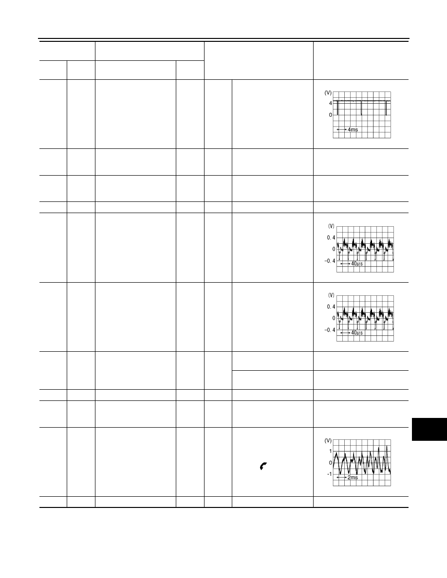
During voice guide output
with the
switch pressed
81
—
Shield
—
—
—
—
Terminal
(Wire color)
Description
Condition
Reference value
(Approx.)
+
–
Signal name
Input/
Output
SKIB3598E
SKIB2251J
SKIB2251J
SKIB3609E

AV-258
< ECU DIAGNOSIS >
[BOSE AUDIO WITHOUT NAVIGATION]
AV CONTROL UNIT
83
(B)
82
(G)
iPod sound signal RH
Input
Ignition
switch
ON
When iPod mode is select-
ed
85
(B)
Ground
Ground
—
Ignition
switch
ON
—
0 V
86
(L)
—
CAN–H
Input/
Output
—
—
—
87
(P)
—
CAN–L
Input/
Output
—
—
—
88
(LG)
—
AV communication signal
(H)
Input/
Output
—
—
—
89
(V)
—
AV communication signal
(L)
Input/
Output
—
—
—
90
(L)
*1
(G)
*2
—
AV communication signal
(H)
Input/
Output
—
—
—
91
(P)
*1
(R)
*2
—
AV communication signal
(L)
Input/
Output
—
—
—
95
(B)
Ground
AUX sound signal RH
Input
Ignition
switch
ON
When AUX mode is select-
ed
96
(R)
Ground
AUX sound signal LH
Input
Ignition
switch
ON
When AUX mode is select-
ed
97
(W)
—
AUX sound signal ground
—
—
—
—
99
(R)
98
(W)
iPod sound signal LH
Input
Ignition
switch
ON
When iPod mode is select-
ed
Terminal
(Wire color)
Description
Condition
Reference value
(Approx.)
+
–
Signal name
Input/
Output
SKIB3609E
SKIB3609E
SKIB3609E
SKIB3609E
AV
AV CONTROL UNIT
AV-259
< ECU DIAGNOSIS >
[BOSE AUDIO WITHOUT NAVIGATION]
C
D
E
F
G
H
I
J
K
L
M
B
A
O
P
101
(BR)
Ground
SW ground
—
Ignition
switch
ON
—
0 V
103
(SB)
Ground
Disk eject signal
Input
—
Pressing the eject switch
0 V
Except for above
3.3 V
104
(G)
Ground
Ignition signal
Input
Ignition
switch
ON
—
Battery voltage
105
(O)
Ground
Reverse signal
Input
Ignition
switch
ON
R position
12.0 V
Other than R position
0 V
106
(V)
Ground
Parking brake signal
Input
Ignition
switch
ON
Parking brake ON
0 V
Parking brake OFF
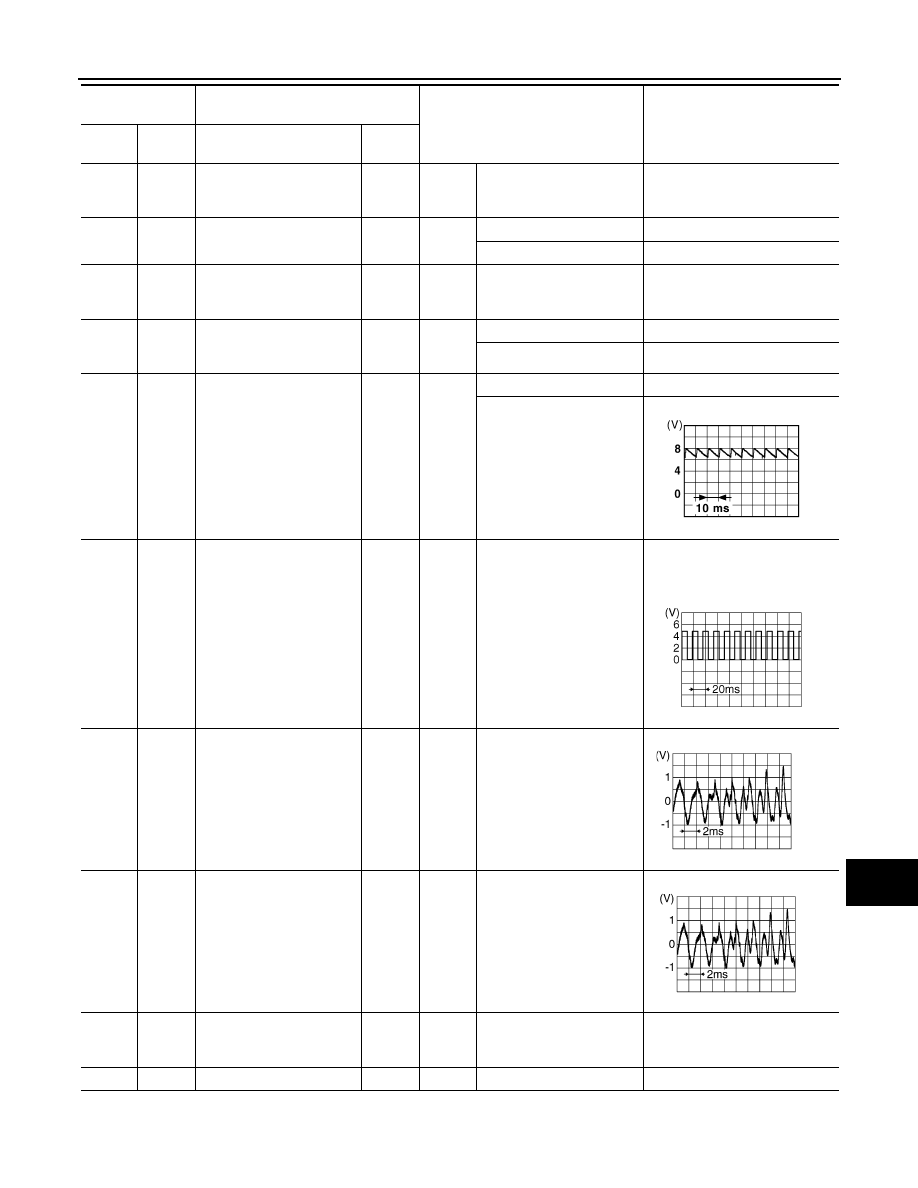
107
(R)
Ground
Vehicle speed signal
(8-pulse)
Input
Ignition
switch
ON
When vehicle speed is ap-
prox. 40 km/h (25 MPH)
NOTE:
Maximum voltage may be 12 V
due to specifications (connected
units).
108
(BR)
114
(Y)
Sound signal rear RH
Output
Ignition
switch
ON
Audio output
109
(R)
115
(G)
Sound signal front RH
Output
Ignition
switch
ON
Audio output
110
(V)
Ground
Amp. ON signal
Output
Ignition
switch
ON
—
10.0 V
111
—
Shield
—
—
—
—
Terminal
(Wire color)
Description
Condition
Reference value
(Approx.)
+
–
Signal name
Input/
Output
JSNIA0007GB
SKIA6649J
SKIB3609E
SKIB3609E
AV-260
< ECU DIAGNOSIS >
[BOSE AUDIO WITHOUT NAVIGATION]
AV CONTROL UNIT
NOTE:
*1: Without rear view monitor.
*2: With rear view monitor.
Wiring Diagram - BOSE AUDIO WITHOUT NAVIGATION SYSTEM -
INFOID:0000000003508730
Click here to view the eWD.
NOTE:
112
(V)
118
(SB)
Sound signal rear LH
Output
Ignition
switch
ON
Audio output
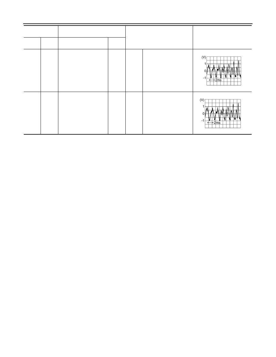
113
(P)
119
(L)
Sound signal front LH
Output
Ignition
switch
ON
Audio output
Terminal
(Wire color)
Description
Condition
Reference value
(Approx.)
+
–
Signal name
Input/
Output
SKIB3609E
SKIB3609E
Нет комментариевНе стесняйтесь поделиться с нами вашим ценным мнением.
Текст