Infiniti EX35. Manual — part 117
AV
STEERING SWITCH SIGNAL B CIRCUIT
AV-249
< COMPONENT DIAGNOSIS >
[BOSE AUDIO WITHOUT NAVIGATION]
C
D
E
F
G
H
I
J
K
L
M
B
A
O
P
STEERING SWITCH SIGNAL B CIRCUIT
Description
INFOID:0000000003544799
Transmits the steering switch signal to AV control unit.
Diagnosis Procedure
INFOID:0000000003544800
1.
CHECK STEERING SWITCH SIGNAL B CIRCUIT
1.
Disconnect AV control unit connector and spiral cable connector.
2.
Check continuity between AV control unit harness connector and spiral cable harness connector.
3.
Check continuity between AV control unit harness connector and ground.
Is the inspection result normal?
YES
>> GO TO 2.
NO
>> Repair harness or connector.
2.
CHECK SPIRAL CABLE
Check spiral cable.
Is the inspection result normal?
YES
>> GO TO 3.
NO
>> Replace spiral cable.
3.
CHECK AV CONTROL UNIT VOLTAGE
1.
Connect AV control unit connector and spiral cable connector.
2.
Turn ignition switch ON.
3.
Check voltage between AV control unit harness connector.
Is the inspection result normal?
YES
>> GO TO 4.
NO
>> Replace AV control unit.
4.
CHECK STEERING SWITCH
1.
Turn ignition switch OFF.
2.
Check steering switch. Refer to
AV-250, "Component Inspection"
Is the inspection result normal?
YES
>> INSPECTION END
NO
>> Replace steering switch.
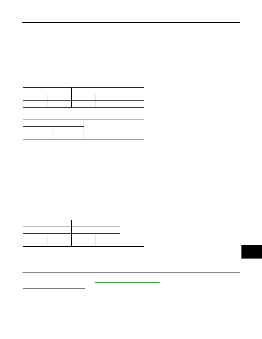
AV control unit
Spiral cable
Continuity
Connector
Terminal
Connector
Terminal
M81
16
M36
31
Existed
AV control unit
Ground
Continuity
Connector
Terminal
M81
16
Not existed
(+)
(
−
)
Reference
value
(Approx.)
AV control unit
AV control unit
Connector
Terminal
Connector
Terminal
M81
16
M81
15
3.3 V

AV-250
< COMPONENT DIAGNOSIS >
[BOSE AUDIO WITHOUT NAVIGATION]
STEERING SWITCH SIGNAL B CIRCUIT
Component Inspection
INFOID:0000000003756525
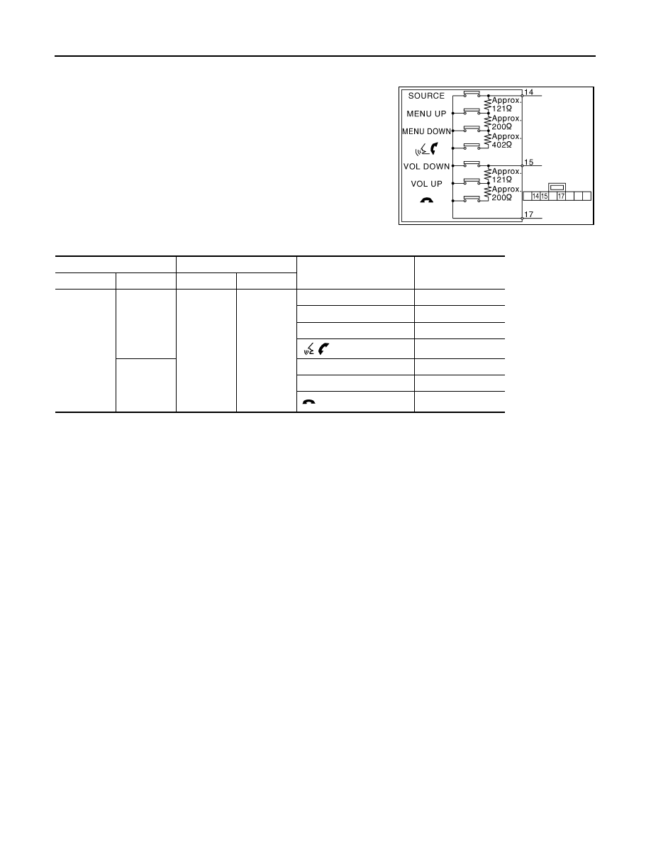
Measure the resistance between the steering switch connector.
JSNIA0216GB
Steering switch
Steering switch
Condition
Resistance value
(
Ω
)
Connector
Terminal
Connector
Terminal
M303
14
M303
17
SOURCE switch ON
0
MENU UP switch ON
120 – 122
MENU DOWN switch ON
318 – 324
switch ON
716 – 730
15
VOL DOWN switch ON
0
VOL UP switch ON
120 – 122
switch ON
318 – 324
AV
STEERING SWITCH SIGNAL GND CIRCUIT
AV-251
< COMPONENT DIAGNOSIS >
[BOSE AUDIO WITHOUT NAVIGATION]
C
D
E
F
G
H
I
J
K
L
M
B
A
O
P
STEERING SWITCH SIGNAL GND CIRCUIT
Description
INFOID:0000000003544801
Transmits the steering switch signal to AV control unit.
Diagnosis Procedure
INFOID:0000000003544802
1.
CHECK STEERING SWITCH SIGNAL GND CIRCUIT
1.
Disconnect AV control unit connector and spiral cable connector.
2.
Check continuity between AV control unit harness connector and spiral cable harness connector.
3.
Connect AV control unit connector.
Is the inspection result normal?
YES
>> GO TO 2.
NO
>> Repair harness or connector.
2.
CHECK SPIRAL CABLE
Check spiral cable.
Is the inspection result normal?
YES
>> GO TO 3.
NO
>> Replace spiral cable.
3.
CHECK GROUND CIRCUIT
1.
Connect AV control unit connector.
2.
Check continuity between AV control unit harness connector and ground.
Is the inspection result normal?
YES
>> GO TO 4.
NO
>> Replace AV control unit.
4.
CHECK STEERING SWITCH
1.
Turn ignition switch OFF.
2.
Check steering switch. Refer to
AV-252, "Component Inspection"
Is the inspection result normal?
YES
>> INSPECTION END
NO
>> Replace steering switch.
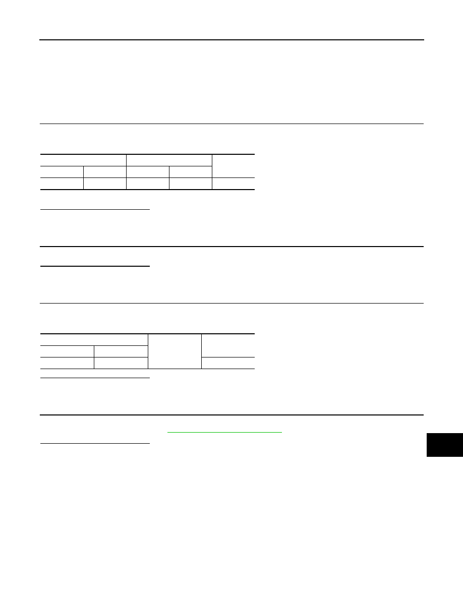
AV control unit
Spiral cable
Continuity
Connector
Terminal
Connector
Terminal
M81
15
M36
33
Existed
AV control unit
Ground
Continuity
Connector
Terminal
M81
15
Not existed
AV-252
< COMPONENT DIAGNOSIS >
[BOSE AUDIO WITHOUT NAVIGATION]
STEERING SWITCH SIGNAL GND CIRCUIT
Component Inspection
INFOID:0000000003756526
Measure the resistance between the steering switch connector.
JSNIA0216GB
Steering switch
Steering switch
Condition
Resistance value
(
Ω
)
Connector
Terminal
Connector
Terminal
M303
14
M303
17
SOURCE switch ON
0
MENU UP switch ON
120 – 122
MENU DOWN switch ON
318 – 324
switch ON
716 – 730
15
VOL DOWN switch ON
0
VOL UP switch ON
120 – 122
switch ON
318 – 324
Нет комментариевНе стесняйтесь поделиться с нами вашим ценным мнением.
Текст