Infiniti EX35. Manual — part 349
ABS ACTUATOR AND ELECTRIC UNIT (CONTROL UNIT)
BRC-111
< ON-VEHICLE REPAIR >
[VDC/TCS/ABS]
C
D
E
G
H
I
J
K
L
M
A
B
BRC
N
O
P
INSTALLATION
Note the following, and install in the reverse order of removal.
CAUTION:
• Before servicing, disconnect the battery cable from negative terminal.
• To remove brake tube, use a flare nut wrench to prevent flare nuts and brake tube from being dam-
aged. To install, use flare nut crowfoot and torque wrench.
• Do not apply excessive impact to ABS actuator and electric unit (control unit), such as dropping it.
• Do not remove and install actuator by holding harness.
• After work is completed, bleed air from brake tube. Refer to
BR-11, "Bleeding Brake System"
• After installing harness connector in the ABS actuator and electric unit (control unit), make sure
connector is securely locked.
• When replacing ABS actuator and electric unit (control unit), make sure to adjust neutral position of
steering angle sensor. Refer to
BRC-112
< ON-VEHICLE REPAIR >
[VDC/TCS/ABS]
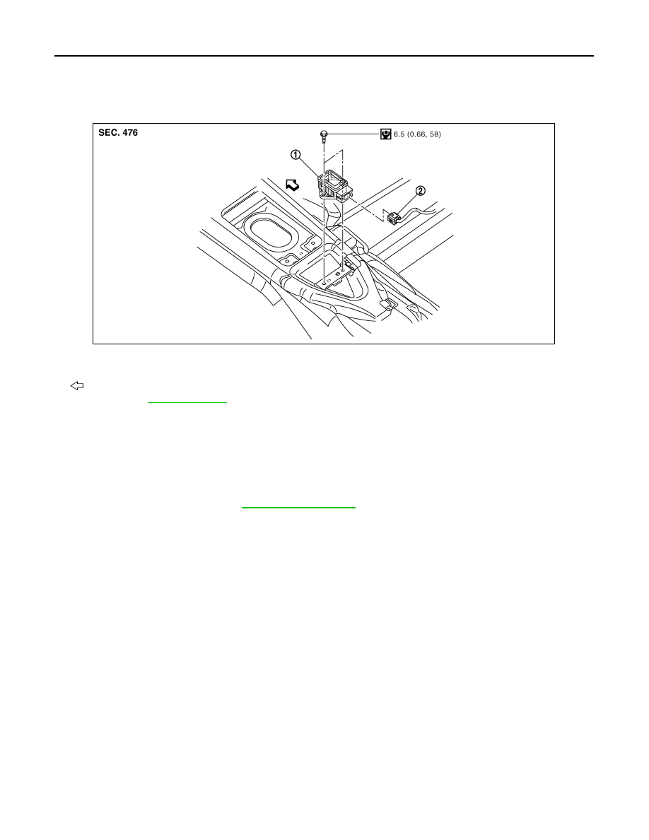
YAW RATE/SIDE G SENSOR
YAW RATE/SIDE G SENSOR
Exploded View
INFOID:0000000003133009
Removal and Installation
INFOID:0000000003133010
REMOVAL
CAUTION:
Do not drop or strike yaw rate/side G sensor, or do not use power tool etc., because yaw rate/side G
sensor is sensitive to the impact.
1.
Remove center console. Refer to
2.
Disconnect yaw rate/side G sensor harness connector.
3.
Remove mounting bolts. Remove yaw rate/side G sensor.
INSTALLATION
Note the following, and install in the reverse order of removal.
CAUTION:
Do not drop or strike yaw rate/side G sensor, or do not use power tool etc., because yaw rate/side G
sensor is sensitive to the impact.
1.
Yaw rate/side G sensor
2.
Connector
: Vehicle front
Refer to GI section
for symbol makes in the figure.
JSFIA0197GB
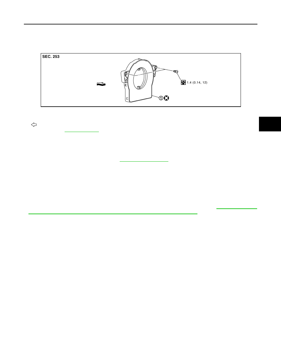
STEERING ANGLE SENSOR
BRC-113
< ON-VEHICLE REPAIR >
[VDC/TCS/ABS]
C
D
E
G
H
I
J
K
L
M
A
B
BRC
N
O
P
STEERING ANGLE SENSOR
Exploded View
INFOID:0000000003133011
Removal and Installation
INFOID:0000000003133012
REMOVAL
1.
Remove spiral cable assembly. Refer to
2.
Remove steering angle sensor from spiral cable assembly.
INSTALLATION
Note the following, and install in the reverse order of removal.
CAUTION:
• Never reuse steering angle sensor.
• When installing steering angle sensor, tighten it to the specified torque with an electric screwdriver.
Be sure to tighten it completely with no floating and tilting.
• After work, make sure to adjust neutral position of steering angle sensor. Refer to
MENT OF STEERING ANGLE SENSOR NEUTRAL POSITION : Description"
1.
Steering angle sensor
: Vehicle front
Refer to GI section
for symbol marks in the figure.
JSFIA0237GB
BRM-1
BODY EXTERIOR, DOORS, ROOF & VEHICLE SECURITY
C
D
E
F
G
H
I
J
L
M
SECTION
BRM
A
B
BRM
N
O
P
CONTENTS
BODY REPAIR
FEATURES OF NEW MODEL . . . . . ..
BODY EXTERIOR PAINT COLOR . . . . . .
Body Exterior Paint Color . . . . . . . . . ...
PRECAUTION . . . . . . . . . . . ...
HANDLING PRECAUTIONS . . . . . . . ...
Precautions For Plastics . . . . . . . . . . ..
REMOVAL AND INSTALLATION . . . .
BODY COMPONENT PARTS . . . . . . . .
Underbody Component Parts . . . . . . . . ..
Body Component Parts . . . . . . . . . . .....
CORROSION PROTECTION . . . . . . . .
Description . . . . . . . . . . . . . . . ..
Anti-corrosive Wax . . . . . . . . . . . . ..
Undercoating . . . . . . . . . . . . . . ...
BODY SEALING . . . . . . . . . . . . .
Description . . . . . . . . . . . . . . . ..
BODY CONSTRUCTION . . . . . . . . .
Body Construction . . . . . . . . . . . . ...
BODY ALIGNMENT . . . . . . . . . . ...
Body Center Marks . . . . . . . . . . . .
Description . . . . . . . . . . . . . . . ...
Engine Compartment . . . . . . . . . . . ..
Underbody (2WD) . . . . . . . . . . . . .
Underbody (AWD) . . . . . . . . . . . . ...
Passenger Compartment . . . . . . . . . .
Rear Body . . . . . . . . . . . . . . . ...
REPAIRING HIGH STRENGTH STEEL . . ...
High Strength Steel (HSS) . . . . . . . . .
REPLACEMENT OPERATIONS . . . . . ...
Description . . . . . . . . . . . . . . . ...
Radiator Core Support . . . . . . . . . . . .
Hoodledge . . . . . . . . . . . . . . . ...
Front Side Member (2WD) . . . . . . . . . ..
Front Side Member (AWD) . . . . . . . . . ..
Front Side Member (Partial Replacement) . . ...
Front Pillar . . . . . . . . . . . . . . . ..
Front Pillar (Partial Replacement) . . . . . . ...
Center Pillar . . . . . . . . . . . . . . . .
Outer Sill . . . . . . . . . . . . . . . . .
Rear Fender . . . . . . . . . . . . . . .
Rear Panel . . . . . . . . . . . . . . . ..
Rear End Crossmember . . . . . . . . . . ..
Rear Floor Rear . . . . . . . . . . . . . .
Нет комментариевНе стесняйтесь поделиться с нами вашим ценным мнением.
Текст