Infiniti EX35. Manual — part 654
EC-358
< COMPONENT DIAGNOSIS >
[VQ35HR]
P1226, P1235 TP SENSOR
P1226, P1235 TP SENSOR
Description
INFOID:0000000003133517
Electric throttle control actuator consists of throttle control motor,
throttle position sensor, etc. The throttle position sensor responds to
the throttle valve movement.
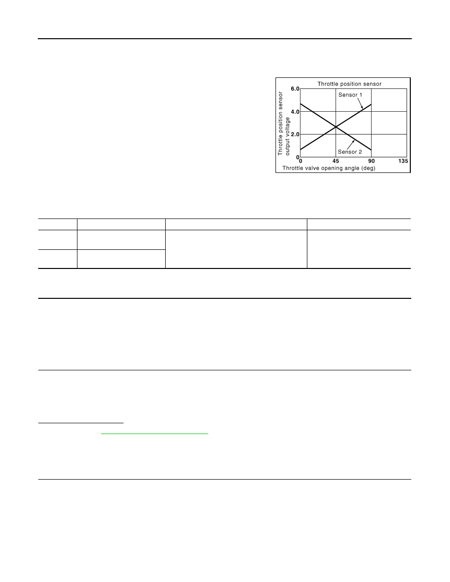
The throttle position sensor has two sensors. These sensors are a
kind of potentiometers which transform the throttle valve position into
output voltage, and emit the voltage signal to the ECM. In addition,
these sensors detect the opening and closing speed of the throttle
valve and feed the voltage signals to the ECM. The ECM judges the
current opening angle of the throttle valve from these signals and the
ECM controls the throttle control motor to make the throttle valve
opening angle properly in response to driving condition.
DTC Logic
INFOID:0000000003133518
DTC DETECTION LOGIC
DTC CONFIRMATION PROCEDURE
1.
PRECONDITIONING
If DTC Confirmation Procedure has been previously conducted, always turn ignition switch OFF and wait at
least 10 seconds before conducting the next test.
TESTING CONDITION:
Before performing the following procedure, confirm that battery voltage is more than 10 V at idle.
>> GO TO 2.
2.
PERFORM DTC CONFIRMATION PROCEDURE
1.
Turn ignition switch ON.
2.
Turn ignition switch OFF and wait at least 10 seconds.
3.
Turn ignition switch ON.
4.
Repeat steps 2 and 3 for 32 times.
5.
Check 1st trip DTC.
Is 1st trip DTC detected?
YES
>> Go to
NO
>> INSPECTION END
Diagnosis Procedure
INFOID:0000000003133519
1.
CHECK ELECTRIC THROTTLE CONTROL ACTUATOR VISUALLY
1.
Turn ignition switch OFF.
2.
Remove the intake air duct.
PBIB0145E
DTC No.
Trouble diagnosis name
DTC detecting condition
Possible cause
P1226
Closed throttle position learn-
ing performance (bank 1)
Closed throttle position learning is not performed
successfully, repeatedly.
• Electric throttle control actuator
(TP sensor 1 and 2)
P1235
Closed throttle position learn-
ing performance (bank 2)

P1226, P1235 TP SENSOR
EC-359
< COMPONENT DIAGNOSIS >
[VQ35HR]
C
D
E
F
G
H
I
J
K
L
M
A
EC
N
P
O
3.
Check if foreign matter is caught between the throttle valve (1)
and the housing.
Is the inspection result normal?
YES
>> GO TO 2.
NO
>> Remove the foreign matter and clean the electric throttle
control actuator inside.
2.
REPLACE ELECTRIC THROTTLE CONTROL ACTUATOR
1.
Replace malfunctioning electric throttle control actuator.
2.
Go to
EC-359, "Special Repair Requirement"
.
>> INSPECTION END
Special Repair Requirement
INFOID:0000000003133520
1.
PERFORM THROTTLE VALVE CLOSED POSITION LEARNING
EC-17, "THROTTLE VALVE CLOSED POSITION LEARNING : Special Repair Requirement"
>> GO TO 2.
2.
PERFORM IDLE AIR VOLUME LEARNING
EC-18, "IDLE AIR VOLUME LEARNING : Special Repair Requirement"
>> END
JMBIA0025ZZ

EC-360
< COMPONENT DIAGNOSIS >
[VQ35HR]
P1233, P2101 ELECTRIC THROTTLE CONTROL FUNCTION
P1233, P2101 ELECTRIC THROTTLE CONTROL FUNCTION
Description
INFOID:0000000003133521
Electric throttle control actuator consists of throttle control motor, throttle position sensor, etc.
The throttle control motor is operated by the ECM and it opens and closes the throttle valve.
The current opening angle of the throttle valve is detected by the throttle position sensor and it provides feed-
back to the ECM to control the throttle control motor to make the throttle valve opening angle properly in
response to driving condition.
DTC Logic
INFOID:0000000003133522
DTC DETECTION LOGIC
NOTE:
If DTC P1233 or P2101 is displayed with DTC P1238, P1290, first perform the trouble diagnosis for DTC
P1238, P2119. Refer to
If DTC P1233 or P2101 is displayed with DTC P2100, P2119, first perform the trouble diagnosis for DTC
P1290, P2100. Refer to
DTC CONFIRMATION PROCEDURE
1.
PRECONDITIONING
If DTC Confirmation Procedure has been previously conducted, always turn ignition switch OFF and wait at
least 10 seconds before conducting the next test.
TESTING CONDITION:
Before performing the following procedure, confirm that battery voltage is more than 11 V when
engine is running.
>> GO TO 2.
2.
PERFORM DTC CONFIRMATION PROCEDURE
1.
Turn ignition switch ON and wait at least 2 seconds.
2.
Start engine and let it idle for 5 seconds.
3.
Check DTC.
Is DTC detected?
YES
>> Go to
NO
>> INSPECTION END
Diagnosis Procedure
INFOID:0000000003133523
1.
CHECK GROUND CONNECTION
1.
Turn ignition switch OFF.
2.
Check ground connection M95. Refer to Ground Inspection in
Is the inspection result normal?
YES
>> GO TO 2.
NO
>> Repair or replace ground connection.
2.
CHECK THROTTLE CONTROL MOTOR RELAY INPUT SIGNAL CIRCUIT-I
Check the voltage between ECM harness connector terminals as follows.
DTC No.
Trouble diagnosis name
DTC detecting condition
Possible cause
P1233
Electric throttle control
performance (bank 2)
Electric throttle control function does not oper-
ate properly.
• Harness or connectors
(Throttle control motor circuit is open or
shorted)
• Electric throttle control actuator
P2101
Electric throttle control
performance (bank 1)

P1233, P2101 ELECTRIC THROTTLE CONTROL FUNCTION
EC-361
< COMPONENT DIAGNOSIS >
[VQ35HR]
C
D
E
F
G
H
I
J
K
L
M
A
EC
N
P
O
Is the inspection result normal?
YES
>> GO TO 9.
NO
>> GO TO 3.
3.
CHECK THROTTLE CONTROL MOTOR RELAY POWER SUPPLY CIRCUIT
1.
Turn ignition switch OFF.
2.
Disconnect ECM harness connector.
3.
Disconnect IPDM E/R harness connector E7.
4.
Check the continuity between IPDM E/R harness connector and ECM harness connector.
5.
Also check harness for short to ground and short to power.
Is the inspection result normal?
YES
>> GO TO 5.
NO
>> GO TO 4.
4.
DETECT MALFUNCTIONING PART
Check the following.
• Harness connectors E3, F1
• Harness connectors F104, F105
• Harness for open or short between ECM and IPDM E/R
>> Repair open circuit or short to ground or short to power in harness or connectors.
5.
CHECK THROTTLE CONTROL MOTOR RELAY INPUT SIGNAL CIRCUIT-II
1.
Check the continuity between IPDM E/R harness connector and ECM harness connector.
2.
Also check harness for short to ground and short to power.
Is the inspection result normal?
YES
>> GO TO 7.
NO
>> GO TO 6.
6.
DETECT MALFUNCTIONING PART
Check the following.
• Harness connectors E3, F1
• Harness for open or short between ECM and IPDM E/R
>> Repair open circuit or short to ground or short to power in harness or connectors.
DTC
ECM
Condition
Voltage (V)
+
–
Connector
Terminal
Connector
Terminal
P1233
F102
52
M107
128
Ignition switch OFF
Approx. 0
Ignition switch ON
Battery voltage
P2101
F101
3
Ignition switch OFF
Approx. 0
Ignition switch ON
Battery voltage
IPDM E/R
ECM
Continuity
Connector
Terminal
Connector
Terminal
E7
70
F101
25
Existed
DTC
IPDM E/R
ECM
Continuity
Connector
Terminal
Connector
Terminal
P1233
E7
54
F102
52
Existed
P2101
F101
3
Нет комментариевНе стесняйтесь поделиться с нами вашим ценным мнением.
Текст