Infiniti EX35. Manual — part 175

AV
CAMERA ASSISTANCE SONAR SYSTEM
AV-481
< FUNCTION DIAGNOSIS >
[BOSE AUDIO WITH NAVIGATION]
C
D
E
F
G
H
I
J
K
L
M
B
A
O
P
Component Description
INFOID:0000000003160627
7.
Front door speaker LH
8.
• Around view monitor control unit
(with around view monitor)
• Camera control unit (with rear view
monitor)
9.
Rear door speaker LH
10. Rear squawker LH
11. BOSE amp.
12. Corner sensor rear LH
13. Woofer
14. • Rear camera (with around view
monitor)
• Rear view camera (with rear view
monitor)
15. Corner sensor rear RH
16. Buzzer
17. Rear squawker RH
18. Antenna base (antenna amp and sat-
ellite antenna)
19. Rear door speaker RH
20. Side camera RH
21. Front door speaker RH
22. Front squawker RH
23. Display unit
24. Steering angle sensor
25. Steering switch
26. Preset switch
27. Sonar control unit (with around view
monitor)
28. iPod connector
29. Auxiliary input jacks
30. AV control unit
31. Multifunction switch
32. iPod adapter
33. GPS antenna
34. Microphone
A.
Under front seat (LH side)
B.
Luggage floor (LH side)
C.
Luggage side RH
D.
Spiral cable part
E.
Cluster lid C removed condition
F.
Rear view of the display unit
G.
Instrument panel rear side
Part name
Description
AROUND VIEW MONITOR CONTROL UNIT
• It supplies power to front camera, rear camera, and side camera. And then it
superimposes the images from each camera and outputs them to display unit.
• Superimposes the guiding line, predicted course line and sonar indicator to the
camera image that outputs to display unit.
• It performs the reception/transmission of communication signal with each cam-
era.
• Inputs the sensor signal from the steering angle sensor, and then controls the
predicted course line.
• It transmits the sonar operation signal from sonar control unit and receives the
sonar information from the sonar control unit via AV communication.
• It transmits the information received/transmitted with the sonar control unit via
AV communication to AV control unit.
SONAR CONTROL UNIT (WITH AROUND VIEW
MONITOR)
• It is connected with around view monitor control unit via AV communication and
receives the sonar operation signal from around view monitor control unit.
• It transmits the sonar detection status to around view monitor control unit via
AV communication.
• It judges the warning level according to the signal from corner sensor and out-
puts the buzzer drive signal.
• Trouble diagnosis is supported with CONSULT-III (K-LINE).
CORNER SENSOR
The obstacle distance is detected. The signal is transmitted to sonar control unit.
BUZZER
The warning buzzer outputs with the signal from sonar control unit.
AV-482
< FUNCTION DIAGNOSIS >
[BOSE AUDIO WITH NAVIGATION]
DIAGNOSIS SYSTEM (AV CONTROL UNIT)
DIAGNOSIS SYSTEM (AV CONTROL UNIT)
Diagnosis Description
INFOID:0000000003465021
MULTIFUNCTION SWITCH AND PRESET SWITCH SELF-DIAGNOSIS FUNCTION
The ON/OFF operation (continuity) of each switch in multifunction switch and preset switch can be checked.
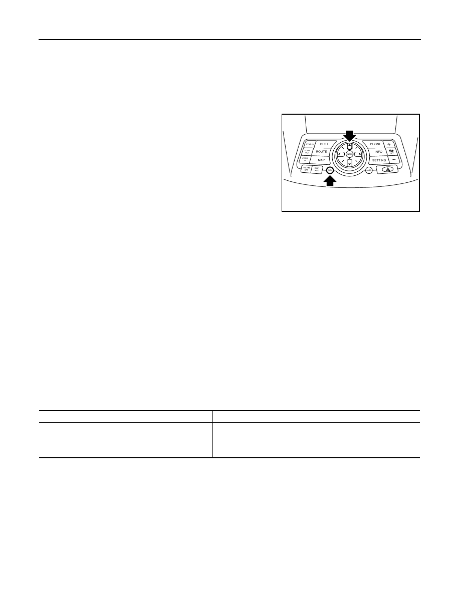
Self-diagnosis mode
• Press the “BACK” switch and the “UP” switch of the 8-direction
switches within 10 seconds after turning the ignition switch from
OFF to ACC and hold them for 3 seconds or more. Then the
buzzer sounds, all indicators of the preset switch illuminate, and
the self-diagnosis mode starts.
• The continuity of each switch in the ON position can be checked by
pressing the switch. The buzzer sounds if the switch is normal.
CAUTION:
The hazard switch and Disk eject switch cannot be checked.
Finishing self-diagnosis mode
Self-diagnosis mode is canceled when turning the ignition switch OFF.
MULTI AV SYSTEM ON BOARD DIAGNOSIS FUNCTION
• AV control unit diagnosis function starts up with multifunction switch operation and AV control unit performs a
diagnosis for each unit in the system during the on board diagnosis.
• Perform a CONSULT-III diagnosis if the on board diagnosis does not start, e.g., the screen does not display
anything, multifunction switch does not function, etc.
ON BOARD DIAGNOSIS
Description
• The trouble diagnosis function has a self-diagnosis mode for conducting trouble diagnosis automatically and
a confirmation/adjustment mode for operating manually.
• The self-diagnosis mode performs diagnoses on AV control unit, connections between system components,
AV control unit and GPS antenna and between AV control unit and satellite radio antenna. Then it displays
the diagnosis results on display.
• The confirmation/adjustment mode allows the technician to check, modify or adjust the vehicle signals and
set values, as well as to monitor the system error records and system communication status. The checking,
modifying or adjusting generally require human intervention and judgment (the system cannot make a judg-
ment automatically).
On board diagnosis item
JSNIA0059GB
Mode
Description
Self Diagnosis
• AV control unit diagnosis
• Diagnoses the connections across system components, between AV
control unit and GPS antenna and between AV control unit and satel-
lite radio antenna.
AV
DIAGNOSIS SYSTEM (AV CONTROL UNIT)
AV-483
< FUNCTION DIAGNOSIS >
[BOSE AUDIO WITH NAVIGATION]
C
D
E
F
G
H
I
J
K
L
M
B
A
O
P
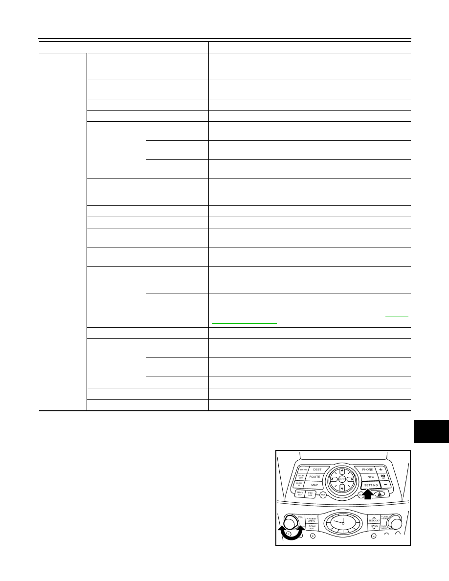
STARTING PROCEDURE
1.
Start the engine.
2.
Turn the audio system OFF.
3.
While pressing the “SETTING” button, turn the volume control
dial clockwise or counterclockwise for 40 clicks or more. (When
the self-diagnosis mode is starts, a short beep will sound.)
• Shifting from current screen to previous screen is performed
by pressing the “BACK” button.
Confirmation/
Adjustment
Display Diagnosis
The following check functions are available: color tone check by color
bar display, light and shade check by gray scale display and touch panel
calibration response check.
Vehicle Signals
Diagnosis of signals can be performed for vehicle speed, parking brake,
lights, ignition switch, and reverse.
Speaker Test
The connection of a speaker can be confirmed by test tone.
Climate Control
Start auto air conditioner system self-diagnosis.
Navigation
Steering Angle Ad-
justment
When there is a difference between the actual turning angle and the ve-
hicle mark turning angle, it can be adjusted.
Speed Calibration
When there is a difference between the current location mark and the ac-
tual location, it can be adjusted.
XM SAT Subscrip-
tion Status
The XM NavTraffic subscription status can be checked.
Error History
The system malfunction and the frequency when occurring in the past
are displayed. When the malfunctioning item is selected, the time and
place that the selected malfunction last occurred are displayed.
Synchronizer FES clock
–
Vehicle CAN Diagnosis
The transmitting/receiving of CAN communication can be monitored.
AV COMM Diagnosis
The communication condition of each unit of Multi AV system can be
monitored.
Handsfree Phone
The received volume adjustment of hands-free phone, microphone
speaker check, and erase memory can be performed.
Camera Cont.
With rear view moni-
tor
The signal connected to camera control unit can be checked and the
guiding line position that overlaps rear view camera image can be adjust-
ed.
With around view
monitor
It can perform the confirmation of a signal connection to around view
monitor control unit, the calibration of each camera, Correct Draw Line
of Camera Image, and Fine Tuning of Birds-Eye View. Refer to
.
Bluetooth
The passkey and the device name can be checked and changed.
SAT
Change Channel
Any necessary channels required to receive traffic information from the
satellite radio system can be set.
Change Application
ID
Any application IDs required to receive traffic information from the satel-
lite radio system can be set.
Diag
Not used.
Delete Unit Connection Log
Erase the connection history of unit and error history.
Initialize Settings
Initializes AV control unit memory.
Mode
Description
JSNIA0060GB
AV-484
< FUNCTION DIAGNOSIS >
[BOSE AUDIO WITH NAVIGATION]
DIAGNOSIS SYSTEM (AV CONTROL UNIT)
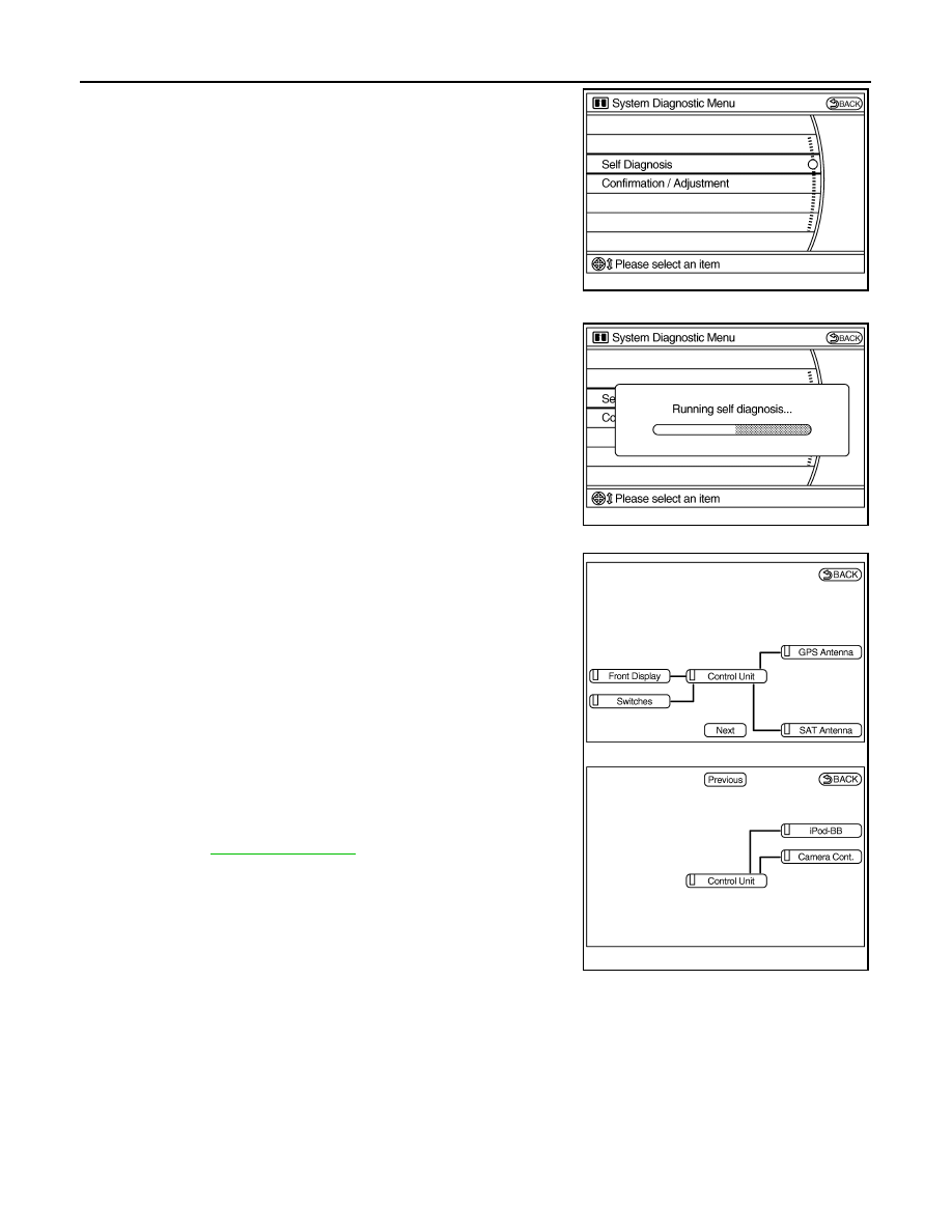
4.
The trouble diagnosis initial screen is displayed, and then the
items of “Self Diagnosis” and “Confirmation/Adjustment” can be
selected.
SELF-DIAGNOSIS MODE
1.
Start the self-diagnosis function and select “Self Diagnosis”.
-
Self-diagnosis subdivision screen is displayed, and the self-
diagnosis mode starts.
-
The bar graph visible on the center of the self-diagnosis subdivi-
sion screen indicates progress of the trouble diagnosis.
2.
Diagnosis results are displayed after the self-diagnosis is com-
pleted. The unit names and the connection lines are color-coded
according to the diagnostic results.
NOTE:
• Only the control unit (AV control unit) is displayed in red.
• Replace AV control unit if “Self-Diagnosis did not run because of a control
unit malfunction” is indicated. The symptom is an AV control unit internal
error. Refer to
.
-
If multiple errors occur at the same time for a single unit, the
screen switch colors are determined according to the following
order of priority: red > gray.
JSNIA0061GB
JSNIA0062GB
Diagnosis results
Unit
Con-
nection
line
Normal
Green
Green
Connection malfunction
Gray
Yellow
Unit malfunction
Note
Red
Green
JSNIA0593GB
Нет комментариевНе стесняйтесь поделиться с нами вашим ценным мнением.
Текст