Infiniti EX35. Manual — part 176
AV
DIAGNOSIS SYSTEM (AV CONTROL UNIT)
AV-485
< FUNCTION DIAGNOSIS >
[BOSE AUDIO WITH NAVIGATION]
C
D
E
F
G
H
I
J
K
L
M
B
A
O
P
-
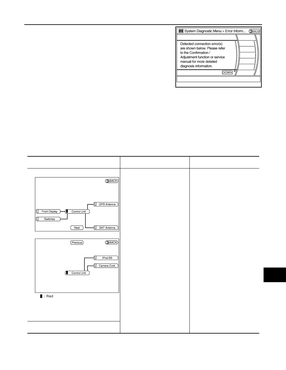
The comments of the self-diagnosis results can be viewed with a
component in the diagnosis result screen.
Detection range of self-diagnosis mode
• The self-diagnosis mode allows the technician to diagnose the connection in the communication line
between AV control unit and each unit and the internal operation of AV control unit.
• Because the start condition of diagnosis function is switch operated, the on board diagnosis function cannot
be started up if any malfunction is detected in the communication circuit between AV control unit and multi-
function switch.
SELF-DIAGNOSIS RESULTS
Check the applicable display in the following table, and then repair the malfunctioning parts.
With Rear View Monitor, With Around View Monitor, Without Rear View Monitor and Around View Monitor (common
item)
JSNIA0064GB
Area with yellow connection lines
Detection logic
Possible malfunction location / Action
to take
NOTE:
When a control unit malfunction is detected (red in
unit display), connection malfunction with other
connection unit may be displayed.
When either one of the following
items are detected:
• AV control unit power supply or
ground circuits malfunction are de-
tected.
• AV control unit malfunction is de-
tected.
• AV control unit power supply and
ground circuits.
• When there is no malfunction, AV
control unit is malfunctioning.
“Self-Diagnosis did not run because of a control unit
malfunction”
JSNIA0594GB
AV-486
< FUNCTION DIAGNOSIS >
[BOSE AUDIO WITH NAVIGATION]
DIAGNOSIS SYSTEM (AV CONTROL UNIT)
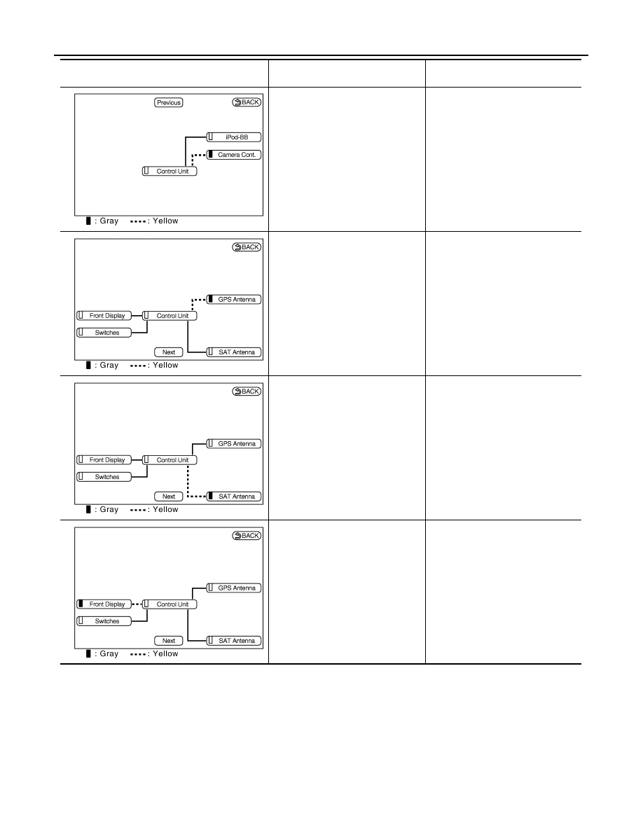
Malfunction is detected in the Cam-
era-connection recognition signal cir-
cuit.
Camera connection recognition signal
circuit.
GPS antenna connection malfunction
is detected.
GPS antenna.
Poor connection is detected in satel-
lite radio antenna.
• Satellite radio antenna feeder.
• Satellite radio antenna.
Malfunction are detected in the com-
munication circuits between AV con-
trol unit and display unit.
Communication circuits between AV
control unit and display unit.
Area with yellow connection lines
Detection logic
Possible malfunction location / Action
to take
JSNIA0596GB
JSNIA0597GB
JSNIA0598GB
JSNIA0599GB
AV
DIAGNOSIS SYSTEM (AV CONTROL UNIT)
AV-487
< FUNCTION DIAGNOSIS >
[BOSE AUDIO WITH NAVIGATION]
C
D
E
F
G
H
I
J
K
L
M
B
A
O
P
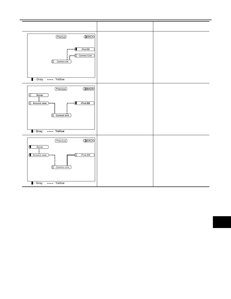
When either one of the following
items are detected:
• iPod adapter power supply or
ground circuits malfunction are de-
tected.
• Malfunction is detected in the AV
communication circuits between
camera control unit and iPod adapt-
er.
• iPod adapter power supply and
ground circuits.
• AV communication circuits between
camera control unit and iPod adapt-
er.
When either one of the following
items are detected:
• iPod adapter power supply or
ground circuits malfunction are de-
tected.
• Malfunction is detected in the AV
communication circuits between
around view monitor control unit
and iPod adapter.
• iPod adapter power supply and
ground circuits.
• AV communication circuits between
around view monitor control unit
and iPod adapter.
Around view monitor control unit pow-
er supply or ground circuits malfunc-
tion are detected.
Around view monitor control unit pow-
er supply and ground circuits
Area with yellow connection lines
Detection logic
Possible malfunction location / Action
to take
JSNIA0600GB
JPNIA1158GB
JSNIA1102GB
AV-488
< FUNCTION DIAGNOSIS >
[BOSE AUDIO WITH NAVIGATION]
DIAGNOSIS SYSTEM (AV CONTROL UNIT)
CONFIRMATION/ADJUSTMENT MODE
1.
Start the diagnosis function and select “Confirmation/Adjustment”. The confirmation/adjustment mode
indicates where each item can be checked or adjusted.
2.
Select each switch on the “Confirmation/Adjustment Mode”
screen to display the relevant trouble diagnosis screen. Press
the “BACK” switch to return to the initial Confirmation/Adjust-
ment Mode screen.
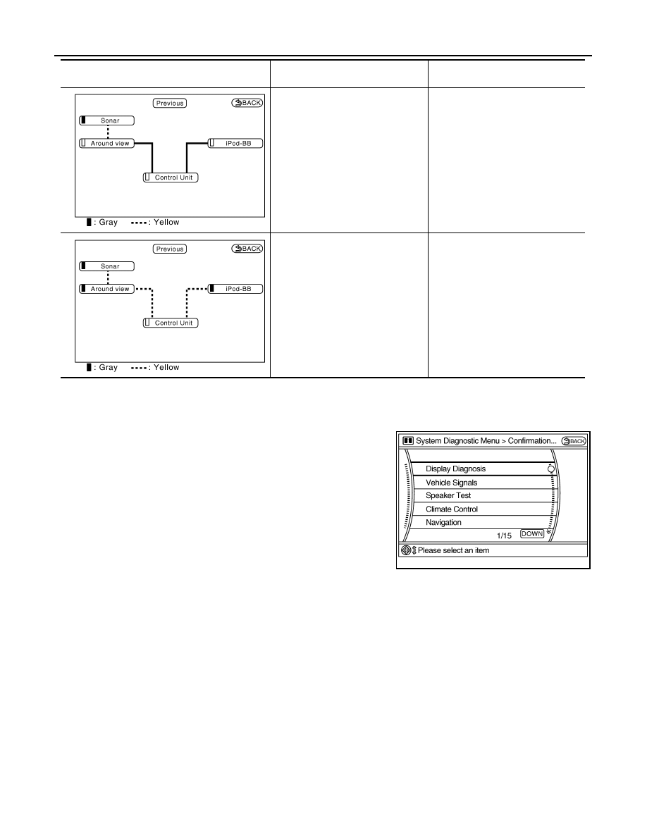
When either one of the following
items are detected:
• Sonar control unit power supply or
ground circuits malfunction are de-
tected.
• Malfunction is detected in the AV
communication circuits between
sonar control unit and the junction
between AV control unit and multi-
function switch.
• Sonar control unit power supply
and ground circuits.
• AV communication circuits between
sonar control unit and the junction
between AV control unit and multi-
function switch.
Malfunction is detected in the AV com-
munication circuits between around
view monitor control unit and the junc-
tion between AV control unit and mul-
tifunction switch.
AV communication circuits between
around view monitor control unit and
the junction between AV control unit
and multifunction switch.
Area with yellow connection lines
Detection logic
Possible malfunction location / Action
to take
JSNIA1104GB
JSNIA1103GB
JSNIA0617GB
Нет комментариевНе стесняйтесь поделиться с нами вашим ценным мнением.
Текст