Infiniti EX35. Manual — part 1093

MWI-50
< COMPONENT DIAGNOSIS >
B2205 VEHICLE SPEED
B2205 VEHICLE SPEED
Description
INFOID:0000000003140195
Vehicle speed signal is transmitted from ABS actuator and electric unit (control unit) via CAN communication
to unified meter and A/C amp.
DTC Logic
INFOID:0000000003140196
DTC DETECTION LOGIC
Diagnosis Procedure
INFOID:0000000003140197
1.
PERFORM SELF-DIAGNOSIS OF ABS ACTUATOR AND ELECTRIC UNIT (CONTROL UNIT)
Perform “Self Diagnostic Result” of ABS actuator and electric unit (control unit), and repair or replace malfunc-
tioning parts.
>> Refer to
BRC-30, "CONSULT-III Function"
.
DTC
Display contents of
CONSULT-III
Diagnostic item is detected when ...
Probable malfunction location
B2205
VEHICLE SPEED
If the abnormal vehicle speed signal is input
from ABS actuator and electric unit (control
unit) for 2 seconds or more
• Wheel sensor
• ABS actuator and electric unit (control unit)

MWI
B2267 ENGINE SPEED
MWI-51
< COMPONENT DIAGNOSIS >
C
D
E
F
G
H
I
J
K
L
M
B
A
O
P
B2267 ENGINE SPEED
Description
INFOID:0000000003140198
The engine speed signal is transmitted from ECM to the unified meter and A/C amp. with CAN communica-
tion.
DTC Logic
INFOID:0000000003140199
DTC DETECTION LOGIC
Diagnosis Procedure
INFOID:0000000003140200
1.
PERFORM SELF-DIAGNOSIS OF ECM
Perform “Self Diagnostic Result” of ECM, and repair or replace malfunctioning parts.
>> Refer to
EC-113, "CONSULT-III Function"
.
DTC
Display contents of
CONSULT-III
Diagnostic item is detected when ...
Probable malfunction location
B2267
ENGINE SPEED
If ECM continuously transmits abnormal en-
gine speed signals for 2 seconds or more
• Crankshaft position sensor (POS)
• ECM

MWI-52
< COMPONENT DIAGNOSIS >
B2268 WATER TEMP
B2268 WATER TEMP
Description
INFOID:0000000003140201
The engine coolant temperature signal is transmitted from ECM to the unified meter and A/C amp. via CAN
communication.
DTC Logic
INFOID:0000000003140202
DTC DETECTION LOGIC
Diagnosis Procedure
INFOID:0000000003140203
1.
PERFORM SELF-DIAGNOSIS OF ECM
Perform “Self Diagnosis Result” of ECM, and repair or replace malfunctioning parts.
>> Refer to
EC-113, "CONSULT-III Function"
.
DTC
Display contents of
CONSULT-III
Diagnostic item is detected when ...
Probable malfunction location
B2268
WATER TEMP
If ECM continuously transmits abnormal en-
gine coolant temperature signals for 60 sec-
onds or more
• Engine coolant temperature sensor
• ECM
MWI
POWER SUPPLY AND GROUND CIRCUIT
MWI-53
< COMPONENT DIAGNOSIS >
C
D
E
F
G
H
I
J
K
L
M
B
A
O
P
POWER SUPPLY AND GROUND CIRCUIT
COMBINATION METER
COMBINATION METER : Diagnosis Procedure
INFOID:0000000003140204
1.
CHECK FUSE
Check for blown fuses.
Is the inspection result normal?
YES
>> GO TO 2.
NO
>> Be sure to eliminate cause of malfunction before installing new fuse.
2.
CHECK POWER SUPPLY CIRCUIT
Check voltage between combination meter harness connector and ground.
Is the inspection result normal?
YES
>> GO TO 3.
NO
>> Check harness between combination meter and fuse.
3.
CHECK GROUND CIRCUIT
1.
Turn ignition switch OFF.
2.
Disconnect combination meter connector.
3.
Check continuity between combination meter harness connector and ground.
Is the inspection result normal?
YES
>> INSPECTION END
NO
>> Repair harness or connector.
UNIFIED METER AND A/C AMP.
UNIFIED METER AND A/C AMP. : Diagnosis Procedure
INFOID:0000000003140205
1.
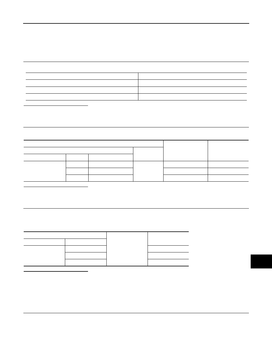
CHECK FUSE
Check for blown fuses.
Power source
Fuse No.
Battery
11
Ignition switch ACC or ON
19
Ignition switch ON or START
4
Terminals
Ignition switch position
Value (Approx.)
(+)
(-)
Combination meter
Terminal
Signal name
M53
1
Battery power supply
Ground
OFF
Battery voltage
23
ACC power supply
ACC
Battery voltage
21
Ignition signal
ON
Battery voltage
Combination meter
Ground
Continuity
Connector
Terminal
M53
5
Existed
15
Existed
22
Existed
Нет комментариевНе стесняйтесь поделиться с нами вашим ценным мнением.
Текст