Infiniti EX35. Manual — part 1094
MWI-54
< COMPONENT DIAGNOSIS >
POWER SUPPLY AND GROUND CIRCUIT
Is the inspection result normal?
YES
>> GO TO 2.
NO
>> Be sure to eliminate cause of malfunction before installing new fuse.
2.
CHECK POWER SUPPLY CIRCUIT
Check voltage between unified meter and A/C amp. harness connector and ground.
Is the inspection result normal?
YES
>> GO TO 3.
NO
>> Check harness between unified meter and A/C amp. and fuse.
3.
CHECK GROUND CIRCUIT
1.
Turn ignition switch OFF.
2.
Disconnect unified meter and A/C amp. connector.
3.
Check continuity between unified meter and A/C amp. harness connector and ground.
Is the inspection result normal?
YES
>> INSPECTION END
NO
>> Repair harness or connector.
BCM (BODY CONTROL MODULE)
BCM (BODY CONTROL MODULE) : Diagnosis Procedure
INFOID:0000000003733134
1.
CHECK FUSE AND FUSIBLE LINK
Check that the following fuse and fusible link are not blown.
Is the fuse fusing?
YES
>> Replace the blown fuse or fusible link after repairing the affected circuit if a fuse or fusible link is
blown.
NO
>> GO TO 2.
2.
CHECK POWER SUPPLY CIRCUIT
1.
Turn ignition switch OFF.
2.
Disconnect BCM connectors.
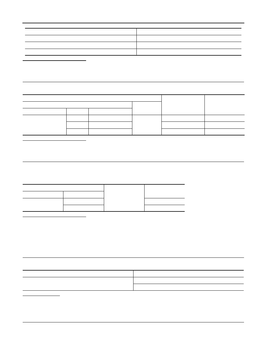
Power source
Fuse No.
Battery
6
Ignition switch ACC or ON
19
Ignition switch ON or START
3
Terminals
Ignition switch position
Value (Approx.)
(+)
(-)
Unified meter A/C amp.
Terminal
Signal name
M67
54
Battery power supply
Ground
OFF
Battery voltage
41
ACC power supply
ACC
Battery voltage
53
Ignition signal
ON
Battery voltage
Unified meter A/C amp.
Ground
Continuity
Connector
Terminal
M67
55
Existed
71
Existed
Signal name
Fuse and fusible link No.
Battery power supply
K
10
MWI
POWER SUPPLY AND GROUND CIRCUIT
MWI-55
< COMPONENT DIAGNOSIS >
C
D
E
F
G
H
I
J
K
L
M
B
A
O
P
3.
Check voltage between BCM harness connector and ground.
Is the measurement value normal?
YES
>> GO TO 3.
NO
>> Repair harness or connector.
3.
CHECK GROUND CIRCUIT
Check continuity between BCM harness connector and ground.
Does continuity exist?
YES
>> INSPECTION END
NO
>> Repair harness or connector.
IPDM E/R (INTELLIGENT POWER DISTRIBUTION MODULE ENGINE ROOM)
IPDM E/R (INTELLIGENT POWER DISTRIBUTION MODULE ENGINE ROOM) : Di-
agnosis Procedure
INFOID:0000000003733135
1.
CHECK FUSES AND FUSIBLE LINK
Check that the following IPDM E/R fuses or fusible links are not blown.
Is the fuse fusing?
YES
>> Replace the blown fuse or fusible link after repairing the affected circuit if a fuse or fusible link is
blown.
NO
>> GO TO 2.
2.
CHECK POWER SUPPLY CIRCUIT
1.
Turn ignition switch OFF.
2.
Disconnect IPDM E/R connector.
3.
Check voltage between IPDM E/R harness connector and ground.
Is the measurement value normal?
YES
>> GO TO 3.
NO
>> Repair harness or connector.
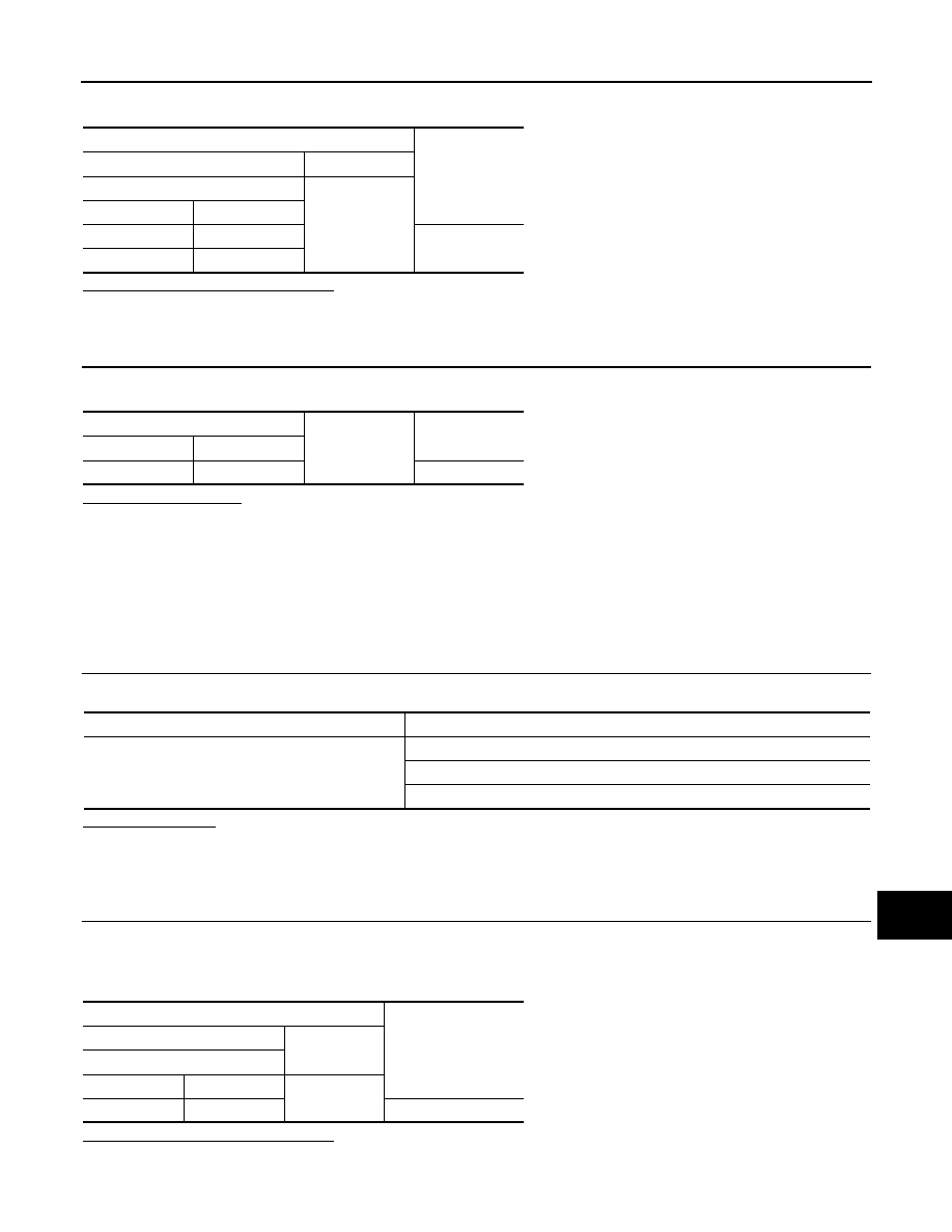
Terminals
Voltage
(Approx.)
(+)
(
−
)
BCM
Ground
Connector
Terminal
M118
1
Battery voltage
M119
11
BCM
Ground
Continuity
Connector
Terminal
M119
13
Existed
Signal name
Fuses and fusible link No.
Battery power supply
C
50
51
Terminals
Voltage
(Approx.)
(+)
(
−
)
IPDM E/R
Connector
Terminal
Ground
E4
1
Battery voltage

MWI-56
< COMPONENT DIAGNOSIS >
POWER SUPPLY AND GROUND CIRCUIT
3.
CHECK GROUND CIRCUIT
Check continuity between IPDM E/R harness connectors and ground.
Does continuity exist?
YES
>> INSPECTION END
NO
>> Repair harness or connector.
IPDM E/R
Ground
Continuity
Connector
Terminal
E5
12
Existed
E6
41
MWI
FUEL LEVEL SENSOR SIGNAL CIRCUIT
MWI-57
< COMPONENT DIAGNOSIS >
C
D
E
F
G
H
I
J
K
L
M
B
A
O
P
FUEL LEVEL SENSOR SIGNAL CIRCUIT
Description
INFOID:0000000003140209
The fuel level sensor unit and fuel pump (main) and the fuel level sensor unit (sub) detect the fuel level in the
fuel tank and transmit the fuel gauge signal to the unified meter and A/C amp.
Component Function Check
INFOID:0000000003140210
1.
CHECK UNIFIED METER AND A/C AMP. OUTPUT SIGNAL
Select the “Data Monitor” for the “METER/M&A” and compare the “FUEL METER” monitor value with the fuel
gauge reading on the combination meter.
Does monitor value match fuel gauge reading?
YES
>> INSPECTION END
NO
>> Replace combination meter.
Diagnosis Procedure
INFOID:0000000003140211
1.
CHECK UNIFIED METER AND A/C AMP. INPUT SIGNAL
1.
Turn ignition switch ON.
2.
Check voltage between unified meter and A/C amp. harness connector and ground.
Does it match fuel gauge reading?
YES
>> GO TO 2.
NO
>> Replace the unified meter and A/C amp.
2.
CHECK FUEL LEVEL SENSOR (SUB) CIRCUIT
1.
Turn ignition switch OFF.
2.
Disconnect unified meter and A/C amp. connector and fuel level sensor unit (sub) connector.
3.
Check continuity between unified meter and A/C amp. harness connector and fuel level sensor unit (sub)
harness connector.
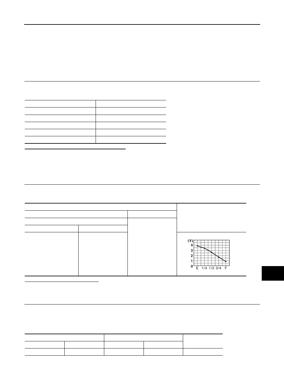
Fuel gauge pointer
Reference value of data monitor [lit.]
Full
Approx. 73.8
Three quarters
Approx. 59.2
Half
Approx. 40.7
A quarter
Approx. 20.9
Empty
Approx. 8.8
Terminals
Voltage
(Approx.)
(+)
(-)
Unified meter and A/C amp.
Ground
Connector
Terminal
M67
42
JSNIA0013GB
Unified meter A/C amp.
Fuel level sensor unit (sub)
Continuity
Connector
Terminal
Connector
terminal
M67
42
B21
1
Existed
Нет комментариевНе стесняйтесь поделиться с нами вашим ценным мнением.
Текст