Infiniti EX35. Manual — part 1083
MWI-10
< FUNCTION DIAGNOSIS >
METER SYSTEM
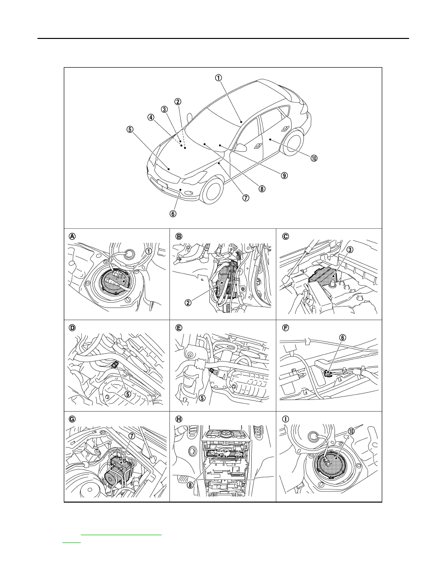
METER SYSTEM : Component Parts Location
INFOID:0000000003140139
1.
Fuel level sensor unit and fuel pump
(main)
2.
BCM
3.
IPDM E/R
4.
ECM :
5.
Oil pressure switch
6.
Ambient sensor
JPNIA0868ZZ

MWI
METER SYSTEM
MWI-11
< FUNCTION DIAGNOSIS >
C
D
E
F
G
H
I
J
K
L
M
B
A
O
P
METER SYSTEM : Component Description
INFOID:0000000003140140
SPEEDOMETER
7.
ABS actuator and electric unit (con-
trol unit)
8.
Unified meter and A/C amp.
9.
Combination meter
10. Fuel level sensor unit (sub)
A.
Rear seat (inside right)
B.
Dash side finisher (passenger side)
C.
Hoodledge cover (RH)
D.
2WD [oil pan (upper) RH side]
E.
AWD (oil filter bracket part)
F.
Condenser (front)
G.
Hoodledge cover (LH)
H.
Behind cluster lid C
I.
Rear seat (inside left)
Unit
Description
Combination meter
Controls the following with the signals from the unified meter and A/C amp, switches and sensors.
• Speedometer
• Tachometer
• Engine coolant temperature gauge
• Fuel gauge
• Warning lamps
• Indicator lamps
• Information display
• Warning chime
Unified meter and A/C amp.
• The combination meter receives the necessary information from various units via CAN communi-
cation line and transmits them to the unified meter and A/C amp. with the communication line that
connects both of them.
• Transmits the fuel gauge signal from the fuel gauge unit with the communication line that connects
the unified meter and A/C amp. and the combination meter.
• Reads the signals from the A/T device transmits them to TCM with CAN communication line.
IPDM E/R
IPDM E/R reads the ON/OFF signals of the oil pressure switch and transmits the oil pressure switch
signal to the unified meter and A/C amp. via BCM with CAN communication line.
Fuel level sensor unit
Oil pressure switch
ECM
Transmits the following signals to the unified meter and A/C amp. with CAN communication line.
• Engine speed signal
• Engine coolant temperature signal
• Fuel consumption monitor signal
ABS actuator and electric unit
(control unit)
Transmits the vehicle speed signal to the unified meter and A/C amp. with CAN communication line.
BCM
• Transmits signals provided by various units to the unified meter and A/C amp. with CAN commu-
nication line.
• Transmits the security signal to the combination meter.
A/T device
Transmits the following signals to the unified meter and A/C amp.
• Manual mode signal
• Not manual mode signal
• Manual mode shift up signal
• Manual mode shift down signal
TCM
Transmits shift position signal to the unified meter and A/C amp.
Meter control switch
Trip A/B reset switch
Washer level switch
Transmits the washer level signal to the combination meter.
Brake fluid level switch
Transmits the brake fluid level switch signal to the combination meter.
Parking brake switch
MWI-12
< FUNCTION DIAGNOSIS >
METER SYSTEM
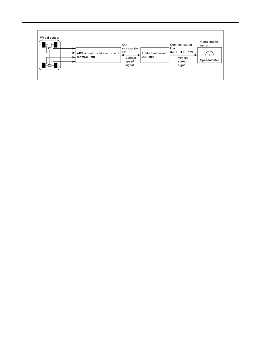
SPEEDOMETER : System Diagram
INFOID:0000000003140141
SPEEDOMETER : System Description
INFOID:0000000003140142
• The ABS actuator and electric unit (control unit) converts the pulse signal provided by the wheel sensor to a
vehicle speed signal and transmits it to the unified meter and A/C amp. with CAN communication line.
• The unified meter and A/C amp. receives the vehicle speed signal from the ABS actuator and electric unit
(control unit) with CAN communication line and transmits it to the combination meter by means of communi-
cation line.
• The combination meter indicates the vehicle speed according to the vehicle speed signal received from the
unified meter and A/C amp. by means of communication line.
JSNIA0158GB
MWI
METER SYSTEM
MWI-13
< FUNCTION DIAGNOSIS >
C
D
E
F
G
H
I
J
K
L
M
B
A
O
P
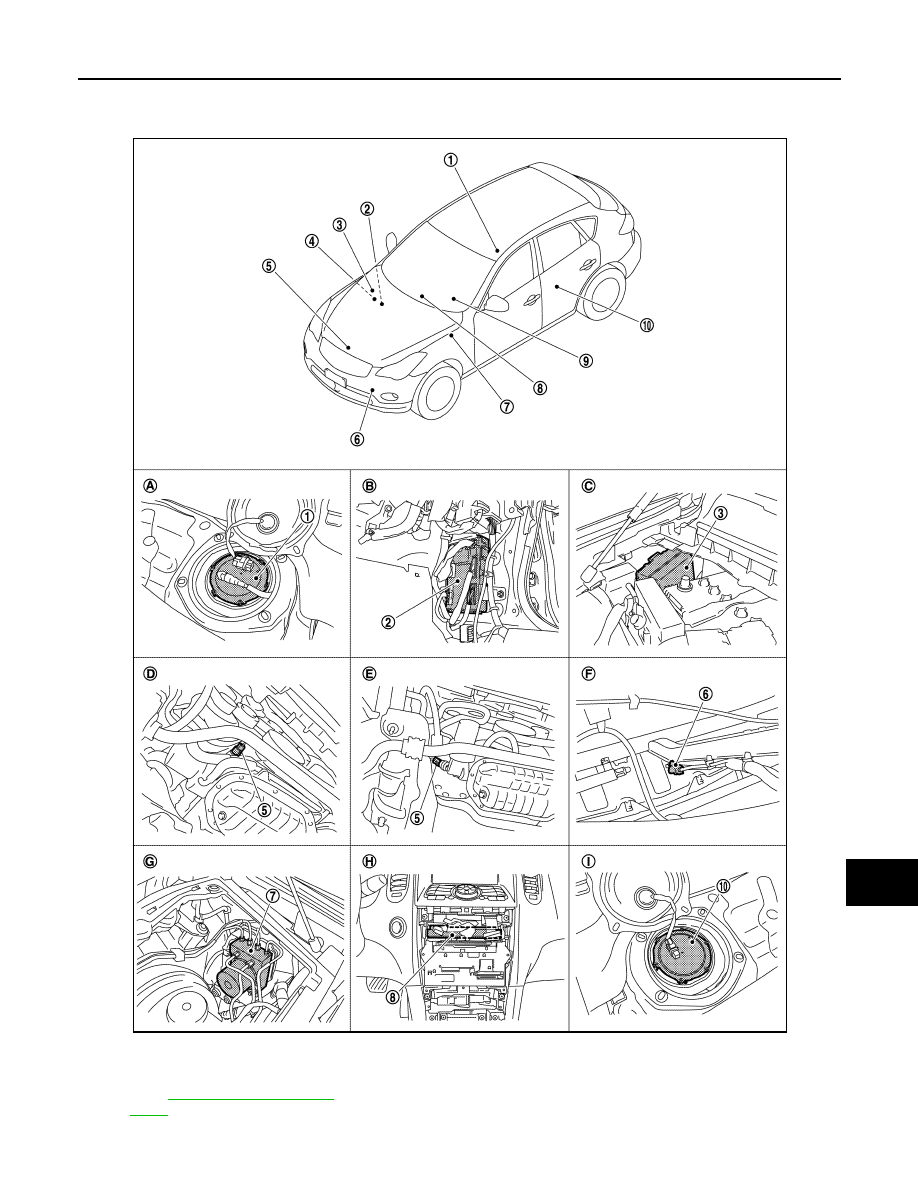
SPEEDOMETER : Component Parts Location
INFOID:0000000003732998
1.
Fuel level sensor unit and fuel pump
(main)
2.
BCM
3.
IPDM E/R
4.
ECM :
5.
Oil pressure switch
6.
Ambient sensor
JPNIA0868ZZ
Нет комментариевНе стесняйтесь поделиться с нами вашим ценным мнением.
Текст