Infiniti EX35. Manual — part 1084
MWI-14
< FUNCTION DIAGNOSIS >
METER SYSTEM
SPEEDOMETER : Component Description
INFOID:0000000003140144
TACHOMETER
TACHOMETER : System Diagram
INFOID:0000000003140145
TACHOMETER : System Description
INFOID:0000000003140146
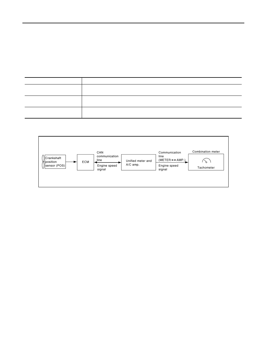
• ECM converts the pulse signal provided by the crankshaft position sensor to an engine speed signal and
transmits it to the unified meter and A/C amp. with CAN communication line.
• Unified meter and A/C amp. transmits engine speed signal to combination meter with communication line.
• The unified meter and A/C amp. receives the engine speed signal from ECM with CAN communication line
and transmits it to the combination meter by means of communication line.
• Combination meter converses engine speed signal to the angle signal, and commands to tachometer.
7.
ABS actuator and electric unit (con-
trol unit)
8.
Unified meter and A/C amp.
9.
Combination meter
10. Fuel level sensor unit (sub)
A.
Rear seat (inside right)
B.
Dash side finisher (passenger side)
C.
Hoodledge cover (RH)
D.
2WD [oil pan (upper) RH side]
E.
AWD (oil filter bracket part)
F.
Condenser (front)
G.
Hoodledge cover (LH)
H.
Behind cluster lid C
I.
Rear seat (inside left)
Unit
Description
Combination meter
Indicates the vehicle speed according to the vehicle speed signal received from the unified meter
and A/C amp. by means of communication line.
Unified meter and A/C amp.
Transmits the vehicle speed signal received from ABS actuator and electric unit (control unit) with
CAN communication line to the combination meter by means of communication line.
ABS actuator and electric unit
(control unit)
Transmits the vehicle speed signal to the unified meter and A/C amp. with CAN communication
line.
JSNIA0160GB
MWI
METER SYSTEM
MWI-15
< FUNCTION DIAGNOSIS >
C
D
E
F
G
H
I
J
K
L
M
B
A
O
P
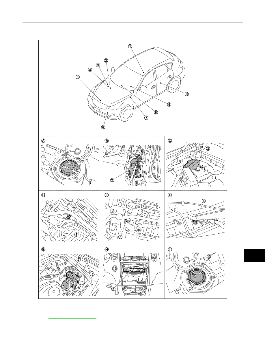
TACHOMETER : Component Parts Location
INFOID:0000000003732997
1.
Fuel level sensor unit and fuel pump
(main)
2.
BCM
3.
IPDM E/R
4.
ECM :
5.
Oil pressure switch
6.
Ambient sensor
JPNIA0868ZZ
MWI-16
< FUNCTION DIAGNOSIS >
METER SYSTEM
TACHOMETER : Component Description
INFOID:0000000003140148
ENGINE COOLANT TEMPERATURE GAUGE
ENGINE COOLANT TEMPERATURE GAUGE : System Diagram
INFOID:0000000003140149
ENGINE COOLANT TEMPERATURE GAUGE : System Description
INFOID:0000000003140150
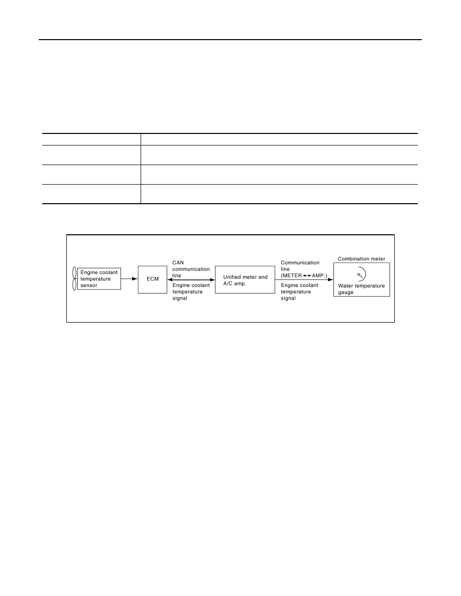
• ECM converses a signal from engine coolant temperature sensor to engine coolant temperature signal, and
transmits to unified meter and A/C amp. with CAN communication line.
• Unified meter and A/C amp. transmits engine coolant temperature signal to combination meter with commu-
nication line.
• Combination meter converses engine coolant temperature signal to the angle signal, and commands to
engine coolant temperature gauge.
7.
ABS actuator and electric unit (con-
trol unit)
8.
Unified meter and A/C amp.
9.
Combination meter
10. Fuel level sensor unit (sub)
A.
Rear seat (inside right)
B.
Dash side finisher (passenger side)
C.
Hoodledge cover (RH)
D.
2WD [oil pan (upper) RH side]
E.
AWD (oil filter bracket part)
F.
Condenser (front)
G.
Hoodledge cover (LH)
H.
Behind cluster lid C
I.
Rear seat (inside left)
Unit
Description
Combination meter
Indicates the engine speed according to the engine speed signal received from the unified meter
and A/C amp. by means of communication line.
Unified meter and A/C amp.
Transmits the engine speed signal received from ECM with CAN communication line to the com-
bination meter by means of communication line.
ECM
Transmits the engine speed signal to the unified meter and A/C amp. with CAN communication
line.
JSNIA0162GB

MWI
METER SYSTEM
MWI-17
< FUNCTION DIAGNOSIS >
C
D
E
F
G
H
I
J
K
L
M
B
A
O
P
ENGINE COOLANT TEMPERATURE GAUGE : Component Parts Location
INFOID:0000000003732999
1.
Fuel level sensor unit and fuel pump
(main)
2.
BCM
3.
IPDM E/R
4.
ECM :
5.
Oil pressure switch
6.
Ambient sensor
JPNIA0868ZZ
Нет комментариевНе стесняйтесь поделиться с нами вашим ценным мнением.
Текст