Seat Mii (2019 year). Manual in english — page 4

Emergencies
case it is lost, another adapter can be or-
You should only change the wheels yourself if
manual gearbox to reduce the risk of the
dered using this number. Note the anti-
the vehicle is parked in a safe place, you are
vehicle moving accidentally.
theft bolt code for the wheels and keep it
familiar with the procedure and safety stand-
● Have the tightening torque of the wheel
in a place other than the vehicle.
ards and you have all the necessary tools!
bolts checked as soon as possible with a
3
Towline anchorage, removable.
Otherwise, you should seek professional as-
reliable torque wrench.
sistance.
4
Wire hook for pulling off the wheel cover,
integral hubcaps and the wheel bolt
WARNING
WARNING
caps.
Changing a wheel can be dangerous, es-
If the wheel trims are not appropriate or not
5
Jack. Before storing the jack in the tool kit,
fitted correctly, they could cause major
pecially on the hard shoulder. Please ob-
fold its hook. The crank must then be fol-
accidents or damage.
serve the following rules to minimise the
ded tight against the side of the jack in
risk of injury:
● Incorrectly mounted wheel trims may
order for it to be safely stored.
● Stop the vehicle safely as soon as possi-
come off while driving and endanger other
6
Wheel spanner.
ble. Park at a safe distance from surround-
road users.
7
Wheel bolt cap clips.
ing traffic to change a wheel.
● Damaged trims must never be mounted
● When changing a wheel, keep all pas-
on the wheels.
Note
sengers, and particularly children, a safe
● Always ensure that the brake ventilation
distance away from the work area.
and cooling is not cut off or blocked. This is
The jack does not generally require any
also valid if hubcaps are fitted later. If there
maintenance. If required, it should be
● Turn on the hazard warning lights to warn
is not enough air, you may require signifi-
greased using universal type grease.
other road users.
cantly longer braking distances.
● Ensure the ground on which you park is
flat and solid. If necessary, support the
jack on a wide solid base.
CAUTION
Changing a wheel
● If you are changing a wheel yourself, you
Remove and remount wheel trims taking
should be familiar with the required proce-
care to avoid damage to the vehicle.
Introduction
dure. Otherwise, you should seek profes-
sional assistance.
Read the additional information carefully
● Only use suitable tools that are not dam-
››› page 37
aged when changing a wheel.
Some vehicle versions and models do not
● Always stop the engine, apply the hand-
have a factory-fitted jack or box spanner. In
brake lever firmly and place the selector
this case, we recommend consulting a Speci-
lever in position N, or engage a gear for a
alised workshop to change the wheel.
72

Self-help
Tyre repair
● If the sealant bottle has passed its use by
● Never use an equivalent jack, even if it
date.
has been approved for your vehicle.
TMS (Tyre Mobility System)*
● Always stop the engine, apply the hand-
WARNING
brake lever firmly and engage gear if using
Read the additional information carefully
Using the tyre mobility system can be dan-
a manual gearbox, in order to reduce the
››› page 36
gerous, especially when filling the tyre at
risk of vehicle involuntary movement.
the roadside. Please observe the following
The Anti-puncture kit* (Tyre Mobility System)
rules to minimise the risk of injury:
WARNING
will reliably seal punctures caused by the
● Stop the vehicle safely as soon as possi-
penetration of a foreign body of up to about
A tyre filled with sealant does not have the
ble. Park it at a safe distance from sur-
4 mm in diameter. Do not remove foreign
same performance properties as a conven-
rounding traffic to fill the tyre.
objects, e.g. screws or nails, from the tyre.
tional tyre.
●
Ensure the ground on which you park is
After inserting the sealant residue in the tyre,
flat and solid.
● Never drive faster than 80 km/h
(50 mph).
you must again check the tyre pressure
● All passengers and particularly children
about 10 minutes after starting the engine.
● Avoid heavy acceleration, hard braking
must keep a safe distance from the work
and fast cornering.
area.
You should only use the tyre mobility set if the
● Drive for only 10 minutes at a maximum
vehicle is parked in a safe place, you are fa-
● Turn on the hazard warning lights to warn
speed of 80 km/h (50 mph) and then check
miliar with the procedure and you have the
other road users.
the tyre.
necessary tyre mobility set! Otherwise, you
● Use the tyre mobility system only if you
should seek professional assistance.
are familiar with the necessary procedures.
Otherwise, you should seek professional
For the sake of the environment
Do not use the tyre sealant in the following
assistance.
Dispose of used or expired sealant observ-
cases:
● The tyre mobility set is intended for tem-
ing any legal requirements.
porary emergency use only until you can
● If the wheel rim has been damaged.
reach the nearest specialised workshop.
● In outside temperatures below -20°C
Note
● Replace the repaired tyre with the tyre
(-4°F).
● A new bottle of sealant can be purchased
mobility set as soon as possible.
● In the event of cuts or perforations in the
at SEAT dealerships.
● The sealant is a health hazard and must
tyre greater than 4 mm.
● Take into account the separate instruc-
be cleaned immediately if it comes into
tion manual of the tyre mobility set* manu-
● If you have been driving with very low pres-
contact with the skin.
facturer.
sure or a completely flat tyre.
● Always keep the tyre mobility set out of
the reach of small children.
73

Emergencies
Contents of the tyre mobility sys-
4
Air compressor
good condition to seal the tyre. Do not con-
tem*
5
Tube for inflating tyres
tinue driving. Seek specialist assistance.
6
Warning provided by tyre pressure moni-
toring system1)
CAUTION
7
Air bleed screw2)
Switch off the air compressor after a maxi-
8
ON/OFF switch
mum of 8 operational minutes to avoid
overheating! Before switching on the air
9
12 volt connector
compressor again, let it cool for several mi-
10
Bottle of sealant
nutes.
11
Spare tyre valve
The valve insert remover 1 has a gap at
Check after 10 minutes of driving
the lower end for a valve insert. The valve in-
sert can only be screwed or unscrewed in this
Screw in the inflator tube ››› Fig. 80 5 again
way. This also applies to its replacement part
and check the pressure on the gauge 6 .
11 .
Fig. 80 Standard display: contents of the anti-
puncture kit.
1.3 bar (19 psi / 130 kPa) and lower:
WARNING
● Stop the vehicle! The tyre cannot be
The anti-puncture kit is located underneath
When inflating the wheel, the air compres-
the floor covering in the luggage compart-
sor and the inflator tube may become hot.
sealed sufficiently with the tyre mobility set.
ment. It includes the following components
● You should obtain professional assistance
● Protect hands and skin from hot parts.
››› Fig. 80:
›››
● Do not place the hot flexible inflator tube
1
Tyre valve remover
or hot air compressor on flammable mate-
1.4 bar (20 psi / 140 kPa) and higher:
rial.
2
A sticker to be adhered to the instrument
● Allow them to cool before storing the de-
● Set the tyre pressure to the correct value
cluster, within the driver's visual field, to
vice.
again ››› page 206.
remind that the maximum advisable
● If it is not possible to inflate the tyre to at
● Carefully resume your journey until you
speed “max. 80 km/h” or “max. 50 mph”
least 2.0 bars (29 psi / 200 kPa), the tyre is
reach the nearest specialised workshop with-
3
Filler tube with cap
too badly damaged. The sealant is not in a
out exceeding 80 km/h (50 mph).
1) It can also be integrated in the compressor.
2) In its place, the compressor may have a button.
74

Self-help
● Have the damaged tyre replaced.
Damaged wiper blades should be replaced
Note
immediately. These are available from quali-
If wax deposits, other cleaning products
WARNING
fied workshops.
from the automatic car wash, or other care
Driving with an unsealed tyre is dangerous
products, are left on the windscreen and
and can cause accidents and serious in-
WARNING
the rear window, the blades can scratch
jury.
Worn or dirty windscreen wiper blades re-
the glass. Remove wax deposits with a spe-
● Do not continue driving if the tyre pres-
duce visibility and increase the risk of acci-
cial product or cleaning cloths.
sure is 1.3 bar (19 psi / 130 kPa) and lower.
dent and serious injury.
● Seek specialist assistance.
● Always replace damaged or worn wind-
screen wiper blades or blades that no lon-
ger clean the windscreen properly.
Tow-starting and towing
Changing the windscreen
CAUTION
Instructions for tow-starting
wiper blades
● Damaged or dirty windscreen wipers
Read the additional information carefully
could scratch the glass.
››› page 43.
Changing the windscreen and rear
● If products containing solvents, rough
sponges or sharp objects are used to clean
When towing or tow starting, respect the le-
window wiper blades
the blades, the graphite layer will be dam-
gal requirements.
aged.
For technical reasons, it is not possible to
Read the additional information carefully
››› page 47.
● Never use fuel, nail varnish remover, paint
tow a vehicle if the battery is flat.
thinner or similar products to clean the win-
In general, the vehicle should not be star-
The windscreen wiper blades are supplied as
dows.
ted by towing. Jump-starting is much more
standard with a layer of graphite. This layer is
responsible for ensuring that the wipe is silent.
preferable ››› page 44.
CAUTION
If the graphite layer is damaged, the noise of
For technical reasons, the following vehicles
the water as it is wiped across the windscreen
● To prevent damage to the bonnet and the
can not be tow started:
wiper arms, only leave them in the service
will be louder.
position.
● Vehicles with an automatic gearbox.
Check the condition of the wiper blades reg-
● Before driving, always lower the wiper
● If the vehicle battery is flat, it is possible that
ularly. If the wipers scrape across the glass
arms.
the engine control unit does not operate cor-
they should be changed if they are dam-
rectly.
»
aged, or cleaned if they are dirty ›››
75
Emergencies
However, if your vehicle must absolutely
erate. Always remain aware to avoid
Advice for towing the vehicle
be tow-started (manual gearbox):
collision with the towing vehicle.
Towing vehicles with an automatic gear-
● Put it into second or third gear.
- More strength is required at the steer-
box
● Keep the clutch pressed down.
ing wheel as the power steering does
not operate when the engine is switch-
Note the following for a towed vehicle:
● Switch on the ignition and the hazard warn-
ed off.
ing lights.
● Make sure the gear selector lever is in the N
● As the driver of the towing vehicle:
● Release the clutch when both vehicles are
position.
- Accelerate gently and carefully.
moving.
● Do not drive faster than 50 km/h (30 mph)
- Avoid sudden braking and manoeuvres.
● As soon as the engine starts, press the
when towing a vehicle.
clutch and move the gear lever into neutral.
- Brake well in advance than usual and
● Do not tow further than 50 km (30 miles).
This helps to prevent a collision with the tow-
brake gently.
● If a breakdown truck is used, the vehicle
ing vehicle.
must be towed with the front wheels raised.
CAUTION
WARNING
● When tow-starting, fuel could enter the
Situations in which a vehicle should not be
A vehicle with a flat battery should never
catalytic converter and damage it.
towed
be towed.
● Carefully fit and remove the towline an-
In the following cases, the vehicle should not
● Never remove the key from the ignition
chorage and its cover to avoid damage to
be towed but transported on a trailer or spe-
lock. Otherwise, the steering wheel lock
the vehicle (e.g. paintwork).
cial vehicle:
could suddenly lock. The vehicle would not
● When towing, fuel could enter the cata-
be controlled and a serious accident could
lytic converter and cause damage!
● If the vehicle gearbox does not contain lu-
ensue.
bricant due to a fault.
Note
● If the battery is flat and the steering cannot
WARNING
be unlocked as a result, the electronic steer-
Fitting a towline anchorage to the rear
When towing the vehicle, the handling and
ing lock and electronic parking brake cannot
bumper is not possible. The vehicle is not
braking efficiency change considerably.
be disengaged.
suitable for towing other vehicles.
Please observe the following instructions
● If the vehicle to be towed has an automatic
to minimise the risk of serious accidents
gearbox and the distance to be covered is
and injury:
greater than 50 km (30 miles).
● As the driver of the vehicle being towed:
- The brake must be depressed must
harder as the brake servo does not op-
76

Self-help
Note
● After towing, remove the tow ring by turning
it clockwise.
The vehicle can only be towed if the steer-
● Place the cover's upper tab on the opening
ing lock electronic gearbox lock is deacti-
vated. If the vehicle has no power supply or
of the bumper and carefully guide the lower
there is an electric system fault, the engine
tab on the edge of the opening. If necessary,
must be started using jump leads to deacti-
press the lower tab from below.
vate the steering column electronic gear-
● Press the lower area of the cover until the
box lock.
lower tab engages in the bumper.
CAUTION
Fig. 82 On the right-hand side of the front
Fitting the front towline anchorage
The towline anchorage must always be
bumper: screw the anchorage.
completely and firmly tightened. Other-
wise, it could be released while towing and
The location for the removable tow ring is on
tow-starting.
the right-hand side of the front bumper be-
hind a cover ››› Fig. 81.
The towline anchorage should always be
kept in the vehicle.
Emergency locking and un-
Note the instructions for towing ››› page 76.
locking
Fitting the towline anchorage
Introduction
● Take the towline anchorage from the vehi-
Fig. 81 On the right-hand side of the front
cle tool kit in the luggage compartment
The doors and rear lid can be locked man-
bumper: remove the lid.
››› page 70.
ually and partially opened, for example if the
key or the central locking is damaged.
● Press the upper part of the cover ››› Fig. 81
(arrow) to disengage and release the cover.
WARNING
● Remove the cover and leave it hanging
Opening and closing doors carelessly can
from the vehicle.
cause serious injury.
● Screw in the tow ring into its housing anti-
● If the vehicle is locked from outside, the
clockwise as far as it will go ››› Fig. 82 ›››
doors and windows cannot be opened from
Use a suitable tool to firmly tighten the tow-
the inside.
»
line anchorage in its location.
77

Emergencies
● Never leave children or disabled people
Fuses and bulbs
● Take care not to cause short circuits in
alone in the car. They could be trapped in
the electrical system.
the car in an emergency and will not be
able to get themselves to safety.
Fuses
WARNING
● Depending on the time of the year, tem-
Using unsuitable fuses, repairing fuses or
peratures inside a locked and closed vehi-
Introduction
bridging a current circuit without fuses can
cle can be extremely high or extremely low
cause a fire and serious injury.
resulting in serious injuries and illness or
Due to the constant updating of vehicles, fuse
even death, particularly for young children.
assignments based on equipment and the
● Never use a fuse with a higher value. Only
use of the same fuse for various electrical
replace fuses with a fuse of the same am-
components, it is not possible to provide an
perage (same colour and markings) and
WARNING
up-to-date summary of the fuse positions for
size.
Getting in the way of the doors and the rear
the electrical components at the time of
● Never repair a fuse.
lid is dangerous and can lead to serious in-
printing this manual. For detailed information
● Never replace a fuse by a metal strip, sta-
jury.
about the fuse positions, please consult a
ple or similar.
● Open and close the doors and the rear lid
technical service.
only when there is nobody in the way.
In general, a fuse can be assigned to various
CAUTION
electrical components. Likewise, an electrical
CAUTION
● To prevent damage to the vehicle's elec-
component can be protected by several
tric system, before replacing a fuse always
When opening and closing in an emergen-
fuses.
turn off the ignition, the lights and all elec-
cy, carefully disassemble components and
trical elements and remove the key from
Only replace fuses when the cause of the
then reassemble them carefully to avoid
the ignition.
problem has been solved. If a newly inserted
damage to the vehicle.
fuse blows after a short time, you must have
● If you replace a fuse with higher-rating
the electrical system checked by a special-
fuse, you could cause damage to another
ised workshop as soon as possible.
part of the electrical system.
● Protect the fuse boxes when open to pre-
WARNING
vent the entry of dust or humidity as they
can damage the electrical system.
The high voltages in the electrical system
can give serious electrical shocks, causing
burns and even death!
Note
● Never touch the electrical wiring of the
● One component may have more than one
ignition system.
fuse.
78
Fuses and bulbs
● Several components may run on a single
Read the additional information carefully
● Protect the fuse boxes when open to
fuse.
››› page 35
avoid the entry of dust or humidity. Dirt and
humidity inside fuse boxes can cause dam-
Only replace fuses with a fuse of the same
age to the electrical system.
amperage (same colour and markings) and
Vehicle fuses
size.
Note
Opening and closing the fuse box situated
In the vehicle, there are more fuses than
below the dash panel
those indicated in this chapter. These
● Open: Press the unlock button ››› Fig. 83
1
should only be changed by a specialised
until it is possible to open the cover. Fold the
workshop.
cover down.
● Close: Fold the cover up in the opposite di-
rection to the arrow until it clicks into the lock-
Changing bulbs
ing lever
1 .
Introduction
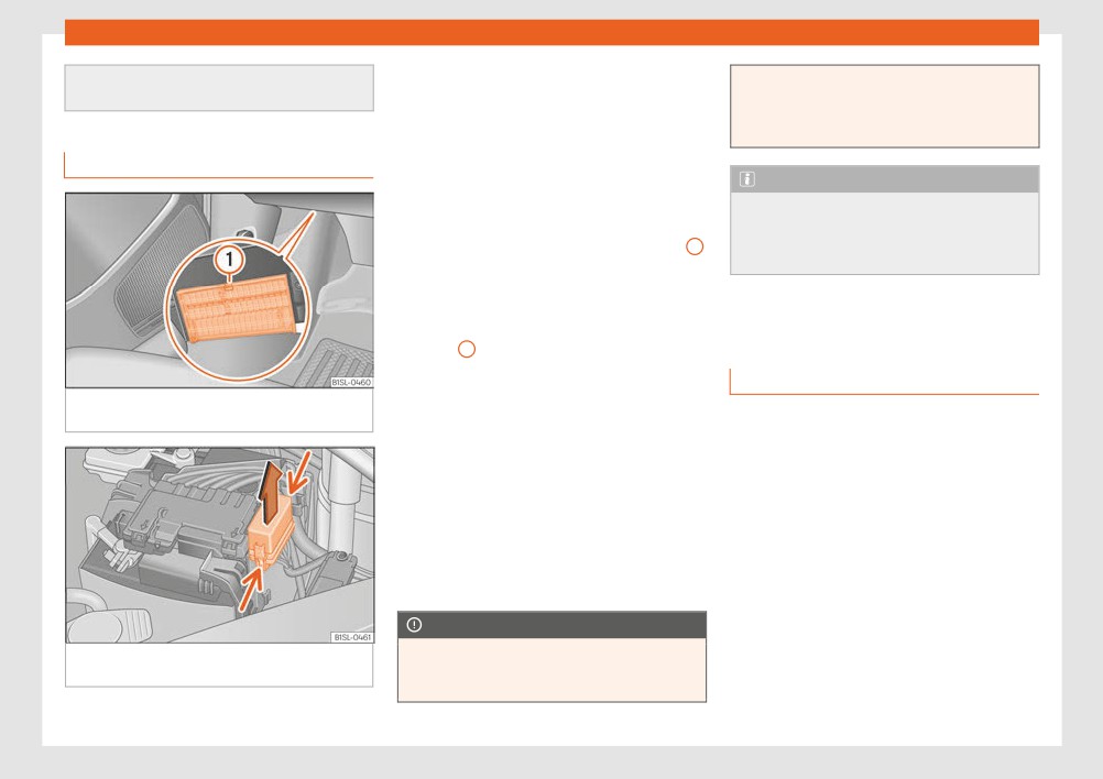
To open the engine compartment fuse box
Fig. 83 Under the dashboard on the driver
side: lid of the fuse box.
● Open the bonnet ››› page 193.
Changing bulbs requires a certain amount of
● Press the attachment tabs in the direction
manual skill. If you are unsure, SEAT recom-
indicated by the arrow (thin arrows) to re-
mends that you consult a technical service or
lease the fuse box cover ››› Fig. 84.
request assistance from a specialist. In gen-
eral a specialist is needed if, in addition to the
● Then lift the cover out.
bulbs, other vehicle components require re-
● To fit the cover, place it on the fuse box.
moval.
Push the attachment tabs down, in the oppo-
site direction indicated by the arrow until they
You should store spare light bulbs in the vehi-
cle for safety-relevant lights. Spare bulbs
click audibly into place.
may be obtained from the technical services.
In some countries, it is a legal requirement to
CAUTION
carry spare bulbs in the vehicle.
Fig. 84 In the engine compartment: lid of the
● Always carefully remove the fuse box
fuse box.
covers and refit them correctly to avoid
Driving with faults and blown bulbs on the ve-
problems with your vehicle.
hicle exterior lighting is against the law.
»
79

Emergencies
Additional bulb specifications
the operating bulb thus “fogging” up the
Replacing the bulbs in the head-
The specifications of some headlamp bulbs
reflector.
lights
and bulbs for the rear lamps fitted at the fac-
● The headlamp frameworks in the engine
tory may be different to those of conventional
compartment and the rear lamps contain
bulbs. Bulb information is displayed on the
sharp elements. Always protect your hands
bulb socket or on the bulb itself.
when changing bulbs.
WARNING
CAUTION
If the road is not well-lit and the vehicle is
● After changing a bulb, if the rubber cov-
not clearly visible to other drivers, there is
ers are not replaced correctly on the head-
a risk of accident.
lamp framework, the electrical installation
may be damaged, especially if water is al-
WARNING
lowed to enter.
Fig. 85 In the engine compartment: Rear view
Failure to replace bulbs correctly may
● Remove the ignition key before working
of the front left headlight with rubber cover: A
cause serious accidents.
on the electric system. Otherwise, a short
dipped beam and main beam headlights, B
circuit could occur.
● Before carrying out any work in the en-
side lights and daytime driving lights and C
gine compartment please read and ob-
● Switch off the lights and the parking light
turn signal
before changing a bulb.
serve the warnings ››› page 193. In any ve-
hicle, the engine compartment is a hazard-
● Take good care to avoid damaging any
ous area and could cause severe injury.
components.
● The bulbs H4, HB4 and H7 are pressurised
and might explode on changing them.
● Only replace the bulbs concerned when
they have cooled.
● Never replace bulbs alone if you are not
familiar with the operations necessary. If
you are not sure about procedures then vis-
it a specialised workshop to carry out the
Fig. 86 Left headlight
necessary work.
● Never touch the bulb glass directly. Fin-
There is no need to remove the headlight to
gerprints will be evaporated by the heat of
replace bulbs.
80

Fuses and bulbs
Complete operations only in the sequence
Side light and daytime lights Fig. 85 B /
given:
Front turn indicator Fig. 85 C
Dipped beam and main beam headlights
Replace the faulty bulb with a new identical
4.
Fig. 85 A
bulb.
1.
Open the bonnet ››› page 193.
5.
Insert the bulb holder in the headlight and turn
it clockwise as far as the stop.
Remove the bulb connector H4. Remove the
rubber cover using the tabs.
Note
2.
Press the retaining clip ››› Fig. 86 D down-
The images show the left hand headlight
wards in the direction of the arrow, unclip side-
from behind. The structure of the right hand
ways, and remove it.
side headlight is symmetric.
Remove the bulb from the holder. If necessary,
Fig. 88 Changing the bulbs in the headlights
3.
press the lock on the bulb holder.
Replace the faulty bulb with a new identical
Replacing the front bumper bulbs
Complete operations only in the se-
4.
bulb.
quence given:
Insert the bulb, return it to its position and insert
Unscrew the 2 retaining screws of the wheel
5.
the retaining clip ››› Fig. 86 D
1.
arch trim ››› Fig. 87 (arrows) with the screwdriv-
er from the vehicle took kit ››› page 70.
Place the rubber cover and check that is in the
6.
correct position. Insert the connector to the
Unscrew the expansive rivet in the lower front
bulb H4.
part of the wheel arch trim A with the screw-
2.
driver from the vehicle tool kit and completely
remove it ››› page 70.
Side light and daytime lights Fig. 85 B /
Front turn indicator Fig. 85 C
3.
Carefully fold the wheel arch trim to the side.
1.
Open the bonnet ››› page 193.
Release the connector ››› Fig. 88
1 and re-
4.
move it.
Turn the bulb holder in an anticlockwise di-
2.
rection as far as it will go and remove it, along
Turn the bulb holder ››› Fig. 88 in the direction
with the bulb, pulling backwards.
Fig. 87 In the front right arch trim: remove the
of the arrow, in an anticlockwise direction as
5.
retaining screws (arrows) and take out the ex-
far as it will go and remove it, along with the
Remove the bulb from the holder. If necessary,
bulb, pulling backwards.
»
3.
pansive rivet A .
press the lock on the bulb holder.
81

Emergencies
Complete operations only in the se-
Changing the bulbs in the rear
quence given:
lights
Replace the faulty bulb with a new identical
6.
bulb.
Insert the bulb holder in the headlight and turn
7.
it clockwise as far as the stop.
Plug the connector
1 into the bulb holder. The
8.
connector must audibly click into place.
9.
Replace the wheel arch trim into its position.
Place the expansive rivet in the wheel arch trim
10.
and bumper and press it completely inwards
››› Fig. 87 A .
Securely screw the 2 retaining screws
11.
››› Fig. 87 (arrows) with a screwdriver.
Fig. 90 Tail light unit: C: remove the bulb hold-
er, D: remove the bulbs.
Complete operations only in the sequence
given.
Removing the rear light units
Fig. 89 On the side of the luggage compart-
ment: A: remove the cover, B: remove the tail
1.
Open the rear lid ››› page 99.
lights.
Carefully remove the cover
1 towards the lever
2.
››› Fig. 89 A.
Pull from the lock 3 in the connector 2 in the
3.
direction of the arrow ››› Fig. 89 B. Use the
screwdriver from the on-board tools.
Press position 4 and remove the connector 2
4.
››› Fig. 89 B.
82

Fuses and bulbs
5.
Unscrew the wing nut 5 ››› Fig. 89 B.
16.
Close the rear lid ››› page 99.
Complete operations only in the se-
quence given:
Remove the tail light from the bodywork by
6.
carefully pulling backwards.
With one hand, press on the number plate light
Changing the number plate light
1.
from left to right and remove it from the bumper
Disassemble the tail light unit and place it on a
7.
››› Fig. 91.
flat, clean surface.
Detach the number plate light carefully from
2.
To change the bulb
the bumper.
Turn the bulb holder with the bulb anticlock-
Unlock the bulb holder locking tab (arrow)
3.
wise and remove it in the direction of the arrow
8.
››› Fig. 90 C and remove the bulb holder from
the tail light.
››› Fig. 92.
Replace the faulty bulb by a new identical bulb
4.
Replace the faulty bulb with a new identical
9.
bulb.
››› Fig. 90 D.
Place the bulb holder in the tail light unit. The
Place the bulb holder in the number plate light
5.
and press in the opposite direction to the arrow
10.
attachment tabs (arrow) should audibly click
into place ››› Fig. 90 C.
Fig. 91
In the rear bumper: remove the plate
as far as possible ››› Fig. 92.
light.
Insert the number plate light carefully into the
Assembling the rear light units
left edge of the opening on the bumper. During
6.
this process, check that the assembly direction
Carefully insert the tail light unit into the open-
of the number plate light is correct, i.e. the
11.
ing in the bodywork.
spring must be on the right.
Support the tail light with one hand in the as-
Insert the number plate light into the bumper
7.
12.
sembly position and securely screw the wing
until it audibly clicks into place.
nut with the other 5 ››› Fig. 89 B.
Ensure that the tail light unit has been correctly
13.
fitted and is firmly secured.
Insert the connector 2 into the bulb holder
14.
and press the lock 3 on the connector in the
Fig. 92 Number plate light: detach the bulb
opposite direction to the arrow ››› Fig. 89 B.
holder.
Insert the cover. The cover should lock into
15.
place.
83

Emergencies
Changing the side turn signal bulb
Complete operations only in the se-
quence given:
Remove the bulb holder with the bulb in the di-
3.
rection of the arrow ››› Fig. 94
1 .
Remove the bulb holder bulb in a straight direc-
4.
tion.
Replace the faulty bulb with a new identical
5.
bulb.
6. Install the bulb holder.
Place the side turn signal on the chassis on the
Fig. 93 Removing the side turn signal
side situated towards the rear of the vehicle until
7.
the spring clicks into the other side of the side
turn signal.
Fig. 94 Side turn light: bulb change.
Complete operations only in the se-
quence given:
With one hand move the side turn signal back-
1.
wards ››› Fig. 93
1 .
Remove the side turn signal from the chassis by
2.
leverage 2 .
84

Operation
Fig. 95 Dash panel
86

General instrument panel
– Lever with buttons for controlling
15
Position of passenger front airbag
Operation
the SEAT information system
on the dash panel
60
- , /
24
16
Ashtray*
119
8
Controls for:
General instrument panel
17
12 volt socket or cigarette light-
- Start-Stop system button
170
er*
120, 120
Instrument panel
- Rear window heating button
129
18
Lever for:
- Left seat heating controls
113
- Manual gearbox
159
Key to Fig. 95:
9
Switches for:
- Automatic gearbox
160
1
Door release lever
98
- Heating and fresh air system
129
19
Handbrake
151
2
Turn switch for adjusting the exterior
- Manual air conditioning
129
20
Button for:
mirrors
110
– Climatronic
129
- City Safety Assist function
174
- Exterior mirror adjustment
10
Radio (factory fitted)
133
21
Ignition lock
149
- Exterior mirror heating
11
Controls for:
22
Pedals
158
3
Air vents
129
- Hazard warning lights switch
70
23
Storage compartment
115
4
Lever for
103
- Passenger front airbag off warn-
24
Steering column adjustment lev-
- Turn signals and main beam
ing lamp
60
er
49
headlights
– Right seat heating controls
25
Open bonnet lever
193
- Cruise control system (CCS)
171
or rear window heating button
26
Headlight range control
103
5
Steering wheel with horn and
(alternative position)
113, 129
27
Light switch
103
- Driver airbag
16
12
Storage compartment with drink
28
Central locking button
94
holder in the centre console
119
6
Instrument panel
88, 27
29
Buttons for operating the front elec-
13
Handle of the storage compartment
7
Windscreen wiper/ windscreen
tric windows
101
or storage compartment open1)
115
wash lever
108
14
In the side of the dash panel: Key
- Windscreen wipers
switch for switching off the front
- Rear window wiper
passenger airbag1)
60
1) According to version
87
Operation
Instruments
View of instrument panel
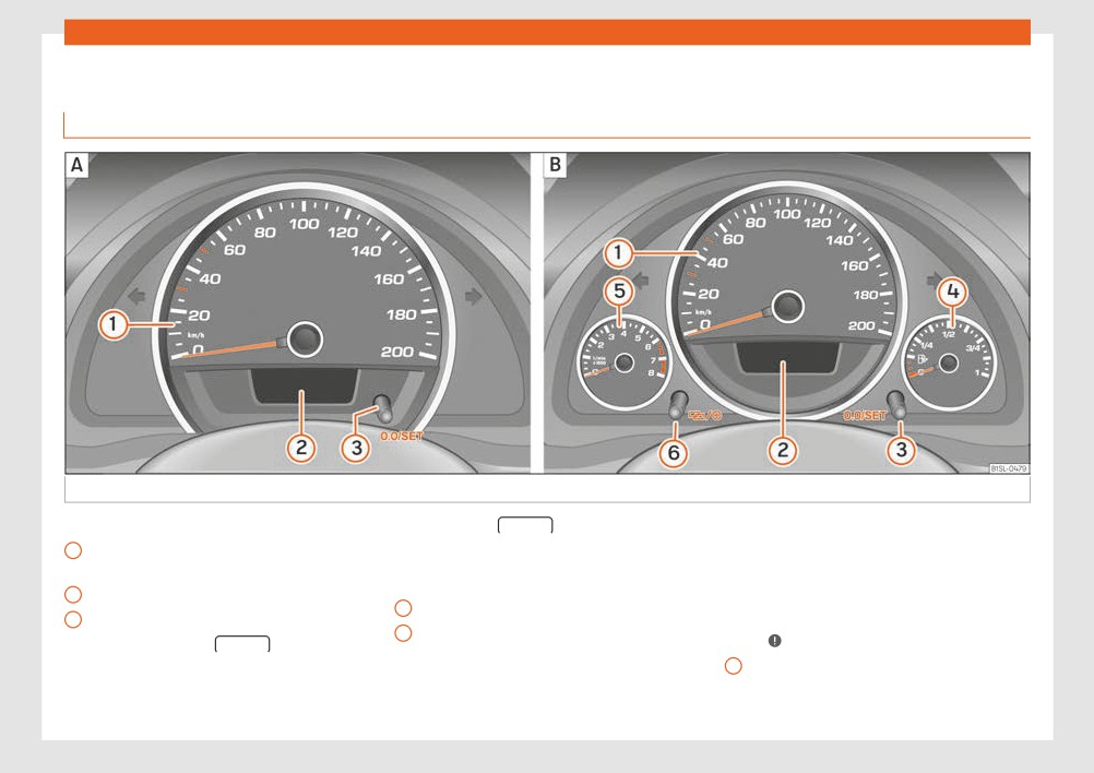
Fig. 96 Instrument panel, on the instrument panel: variant 1 (A) and variant 2 (B).
Details of the instruments ››› Fig. 96:
– Press the 0.0/SET for 5 seconds
speed in any gear after running-in
1
Speedometer. Depending on the
to reset the odometer to zero and,
and with the engine hot. However, it
where necessary, other indicators
is advisable to change up a gear or
vehicle in km/h or in mph.
on the multifunction display
24
move the selector lever to D (or lift
2
Displays on the screen
89
your foot off the accelerator) before
4
Fuel reserve display
189
3
Reset knob for trip recorder (trip).
the needle reaches the red zone
5
Revolution counter (with the en-
- Press the button 0.0/SET briefly
›››
gine running, in thousands of revo-
to switch the trip odometer and
6
Clock set button.
lutions per minute).
odometer.
- If necessary, change the time dis-
The beginning of the red zone of the
rev counter indicates the maximum
play by pressing the top and
88

General instrument panel
bottom buttons of the rocker
Indications on the display
Priority 1 warning (red symbols)
switch ››› Fig. 34 B .
A variety of information can be viewed on the
Symbol flashing or lit; partly combined with audible
- Press the button to change the
warnings.
hour, so that it is flashing.
instrument panel display ››› Fig. 96 2 , de-
Stop the vehicle! It is dangerous ›››
!
pending on the vehicle equipment:
- To continue setting the time, press
Check the function that is faulty and repair it. If nec-
button 0.0/SET . Hold button down
essary, request assistance from specialised person-
● Warning and information messages.
nel.
to scroll through the numbers
● Odometer.
quickly.
● Time.
Priority 2 warning (yellow symbols)
- Press the button again to
change the minutes, so that it
● Outside temperature.
Symbol flashing or lit; partly combined with audible
flashes.
● Selector lever positions ››› page 158.
warnings.
A faulty function, or fluids which are below the cor-
- To continue setting the time, press
● Recommended gear (manual gearbox)
rect levels may cause damage to the vehicle! ›››
button 0.0/SET . Hold button down
››› page 158.
Check the faulty function as soon as possible. If nec-
to scroll through the numbers
essary, request assistance from specialised person-
● Multifunction display (MFI) ››› page 24
quickly.
nel.
● Service interval display››› page 90.
- Press the button again to end
the clock setting.
● Start-Stop system status display
Odometer
››› page 170.
The odometer registers the total distance
CAUTION
● Fuel gauge ››› page 189.
travelled by the car.
● When the engine is cold, avoid high revs
● Seat belt status display for rear seats
The odometer (trip) shows the distance
and heavy acceleration and do not make
››› page 53.
travelled since the last odometer reset. The
the engine work hard.
last figure indicates 100 m.
● To prevent damage to the engine, the rev
Warning and information messages
counter needle should only remain in the
The system runs a check on certain compo-
Outside temperature indicator!
red zone for a short period of time.
nents and functions when the ignition is
When the outside temperature is below +4°C
switched on and while the vehicle is moving.
(+39°F), the “ice crystal” symbol (warning of
For the sake of the environment
Faults in the operation are displayed on the
risk of freezing) is also displayed next to the
screen using red and yellow symbols on the
Changing up a gear in time reduces fuel
temperature. At first this symbol flashes and
instrument panel display (››› page 27)
consumption and noise.
then it remains lit until the outside tempera-
and, in some cases, with audible warnings.
ture rises above +6°C (+43°F) ›››
»
The display may vary according to the type
of instrument panel fitted.
89
Operation
When the vehicle is stationary or travelling at
WARNING
CAUTION
very low speeds, the temperature displayed
If the warning lamps are ignored, the vehi-
Failure to heed the warning lamps when
may be slightly higher than the actual out-
cle may stall in traffic, or may cause acci-
they appear may result in faults in the vehi-
side temperature as a result of heat coming
dents and severe injuries.
cle.
from the engine.
● Never ignore the warning lamps.
The temperatures measured range from
● Stop the vehicle safely as soon as possi-
Note
-40°C to +50°C (-40°F to +122°F).
ble.
● Different versions of the instrument panel
● A faulty vehicle represents a risk of acci-
are available and therefore the versions
Selector lever position
dent for the driver and for other road users.
and instructions on the display may vary.
The range of engaged gears of the selector
If necessary, switch on the hazard warning
● When several warnings are active at the
lever is shown on the side of the lever, and on
lamps and put out the warning triangle to
same time, the symbols are shown succes-
the instrument panel display. In positions D
advise other drivers.
sively for a few seconds and will stay on
and M, and with the Tiptronic, the corre-
● Park the vehicle away from traffic and
until the fault is rectified.
sponding gear is also indicated on the dis-
ensure that no highly flammable materials
play.
are under the vehicle that could come into
contact with the exhaust system (e.g. dry
Recommended gear* (manual gearbox)
grass, fuel).
Service interval display
The recommended gear to save fuel can be
The inspection message appears on the in-
displayed on the instrument panel display
WARNING
strument panel display ››› Fig. 96 2 .
while you are driving ››› page 158.
Even though outside temperatures are
SEAT distinguishes between services with en-
above freezing, some roads and bridges
gine oil change (Oil Change Service) and
Seat belt status display for the rear seats*
may be icy.
services without engine oil change (Inspec-
The seat belt status display on the instrument
● At outside temperatures above +4°C
tion Service). The service interval display only
panel display informs the driver, when the ig-
(+39°F), even when the “ice crystal sym-
gives information for service dates which in-
nition is switched on, whether any passen-
bol” is not visible, there may still be patch-
volve an engine oil change. The dates of the
gers in the rear seats have fastened their seat
es of ice on the road.
remaining services (e.g. the next Inspection
belts ››› page 53.
● Do not rely on the outside temperature
Service or change of brake fluid) are listed on
indicator!
the label attached to the door strut, or in the
Start-Stop system status display
Maintenance Programme.
The instrument panel display shows informa-
The set service intervals have been specified
tion on the current status ››› page 170.
with the service dependent on time/dis-
tance travelled.
90
General instrument panel
Inspection reminder
● In vehicles whose batteries have been
If the inspection period is due to expire short-
disconnected for a long period of time, it
ly, Inspection reminder appears when start-
will not be possible to calculate the next
ing the ignition abbreviated to and a
service date. Therefore the service interval
display may not be correct. In this case,
warning in km. The number of kilometres
bear in mind the maximum service intervals
shown is the maximum number that may be
permitted ››› page 217.
driven until the next service.
● If the period of 48 months for an inspec-
Service due
tion at a specialised workshop of com-
pressed natural gas tanks (CNG) is excee-
After the service date, an audible warning is
ded, the vehicle may not working in this
given when the ignition is switched on and the
mode.
abbreviation displayed on the screen
flashes for a few seconds.
Inspection of compressed natural gas
tanks (CNG) reminder
When less than 90 days for the review of the
compressed natural gas tanks (CNG), when
the ignition is switched on, the instrument
panel display will a reminder for review of
the gas tanks and an audible warning will be
emitted.
As approaches the service date of inspection
of the gas tanks, the message and the audi-
ble warning will stop modify accordingly.
Note
● The service message disappears after a
few seconds, when the engine is started or
when OK is pressed on the windscreen
wiper lever.
91

Operation
Different keys belonging to the vehicle may
doors or the boot hatch, start the engine or
Opening and closing
be used.
turn on the ignition, activating electrical
systems, the electric windows, for example.
Vehicle key set
Folding the key shaft in and out
● Never leave children or disabled people
When the button is pressed ››› Fig. 97 A , the
alone in the car. They could be trapped in
Remote control vehicle key*
key shaft is released and unfolds.
the car in an emergency and will not be
able to get themselves to safety. For exam-
To fold it press the button and fold the key
ple, depending on the time of the year,
shaft in until it locks in place.
temperatures inside a locked and closed
vehicle can be extremely high or extremely
Spare key
low resulting in serious injuries and illness
To obtain a spare key and other vehicle keys,
or even death, particularly for young chil-
dren.
the vehicle chassis number is required.
● Never remove the key from the ignition if
Each new key must contain a microchip and
the vehicle is in motion. The steering may
be coded with the data from the vehicle elec-
lock and it will not be possible to turn the
tronic immobiliser. A vehicle key will not work
steering wheel.
if it does not contain a microchip or the mi-
Fig. 97 Remote control key
crochip has not been encoded. This is also
CAUTION
true for keys cut for the vehicle.
Remote control key
The remote control key contains electronic
The vehicle keys or new spare keys can be
With the vehicle key the vehicle may be
components. Protect them from damage,
obtained from a SEAT dealership, a Special-
impacts and humidity.
locked or unlocked remotely ››› page 94.
ised workshop or approved key service quali-
The vehicle key includes an emitter and bat-
fied to create this kind of key.
Note
tery. The receiver is in the interior of the vehi-
New keys or spare keys must be synchronised
cle. The range of the vehicle key with remote
● Only use the key button when you require
before use ››› page 94.
control and new battery is several metres
the corresponding function. Pushing the
around the vehicle.
button unnecessarily could accidentally
WARNING
unlock the vehicle or trigger the alarm. It is
If it is not possible to open or close the vehicle
Careless or incorrect use of vehicle keys
also possible even when you are outside
using the remote control key, this should be
may result in severe injury and accident.
the radius of action.
re-synchronised ››› page 94 or the battery
● Always take all the keys with you when-
● Remote control key operation can be
changed ››› page 93.
ever you leave the vehicle. Children and
greatly influenced by overlapping radio
unauthorised individuals could lock the
signals around the vehicle working in the
92
Большое спасибо!
Ваше мнение очень важно для нас.
Нет комментариевНе стесняйтесь поделиться с нами вашим ценным мнением.
Текст