Chrysler Le Baron, Dodge Dynasty, Plymouth Acclaim. Manual — part 307
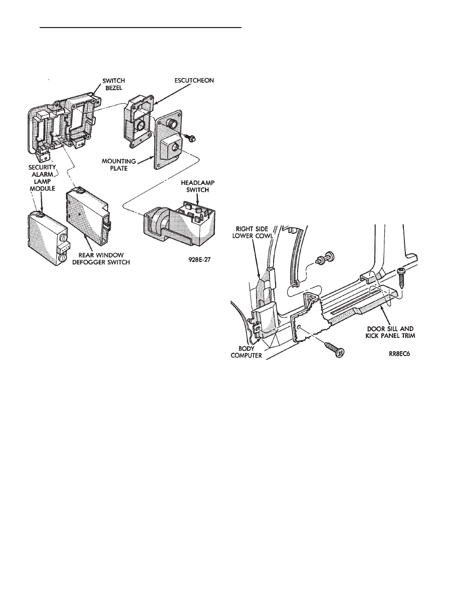
(3) Remove switch assembly and escutcheon from
switch module by removing four attaching screws
(Fig. 37).
(4) Remove headlamp switch mounting plate from
switch by removing retaining nut.
(5) For installation reverse above procedures.
REAR WINDOW DEFOGGER SWITCH
REPLACEMENT
(1) Remove headlamp and accessory switch module
from instrument panel (Fig. 36).
(2) Remove rear window defogger switch by de-
pressing snap-in clips on top and bottom of switch.
(3) For installation reverse above procedures.
HOOD RELEASE HANDLE AND CABLE
REPLACEMENT
(1) Disconnect hood release cable at hood latch.
(2) Remove two screws from underside of hood re-
lease handle.
(3) Pull mechanism assembly rearward to remove.
(4) For installation reverse above procedures.
PARK BRAKE RELEASE HANDLE AND LINK
REPLACEMENT
(1) Remove left side under panel silencer.
(2) Remove park brake link from lever on park
brake mechanism.
(3) Remove upper and lower cluster bezels.
(4) Pull park brake release handle and remove
screw.
(5) Remove column cover/park brake release han-
dle assembly by removing four remaining screws.
(6) For installation reverse above procedures.
LAMP OUTAGE MODULE REPLACEMENT
(1) Disconnect battery negative cable and isolate
or remove fuse #13 prior to removing switch or wires
may short to ground.
(2) Remove lower right instrument panel silencer.
(3) Remove glove box and ash receiver module.
(4) Remove three screws attaching the mounting
bracket to instrument panel.
(5) Lower bracket and module assembly, to discon-
nect wire connectors.
(6) Remove two screws attaching the Lamp Outage
Module to bracket.
(7) Remove two screws attaching the security mod-
ule to bracket.
(8) To installation reverse above procedures.
BODY CONTROLLER REPLACEMENT
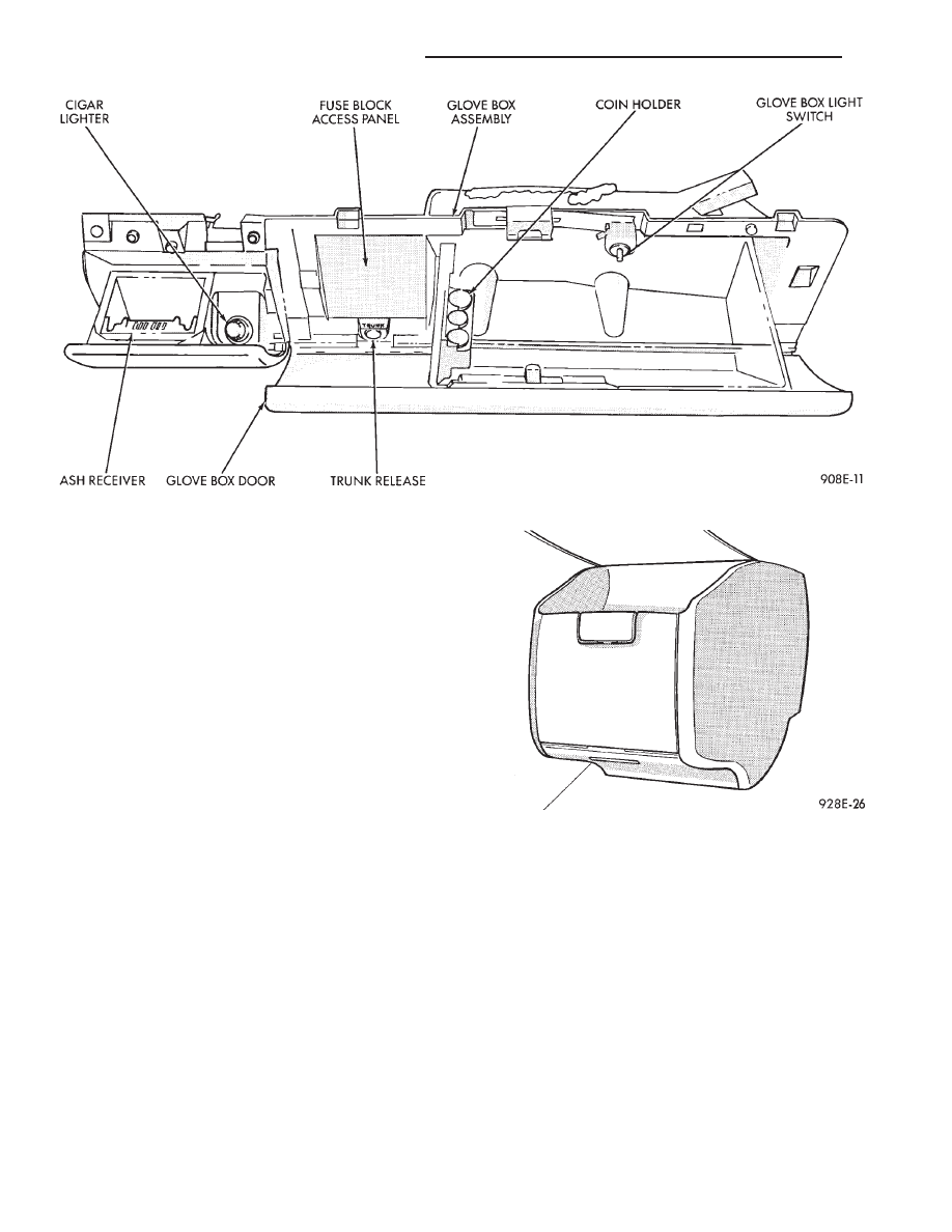
(1) Remove right side door sill and kick panel trim
five screws (Fig. 38).
(2) Disconnect body controller wiring.
(3) Remove controller retaining nuts.
(4) For installation reverse above procedures.
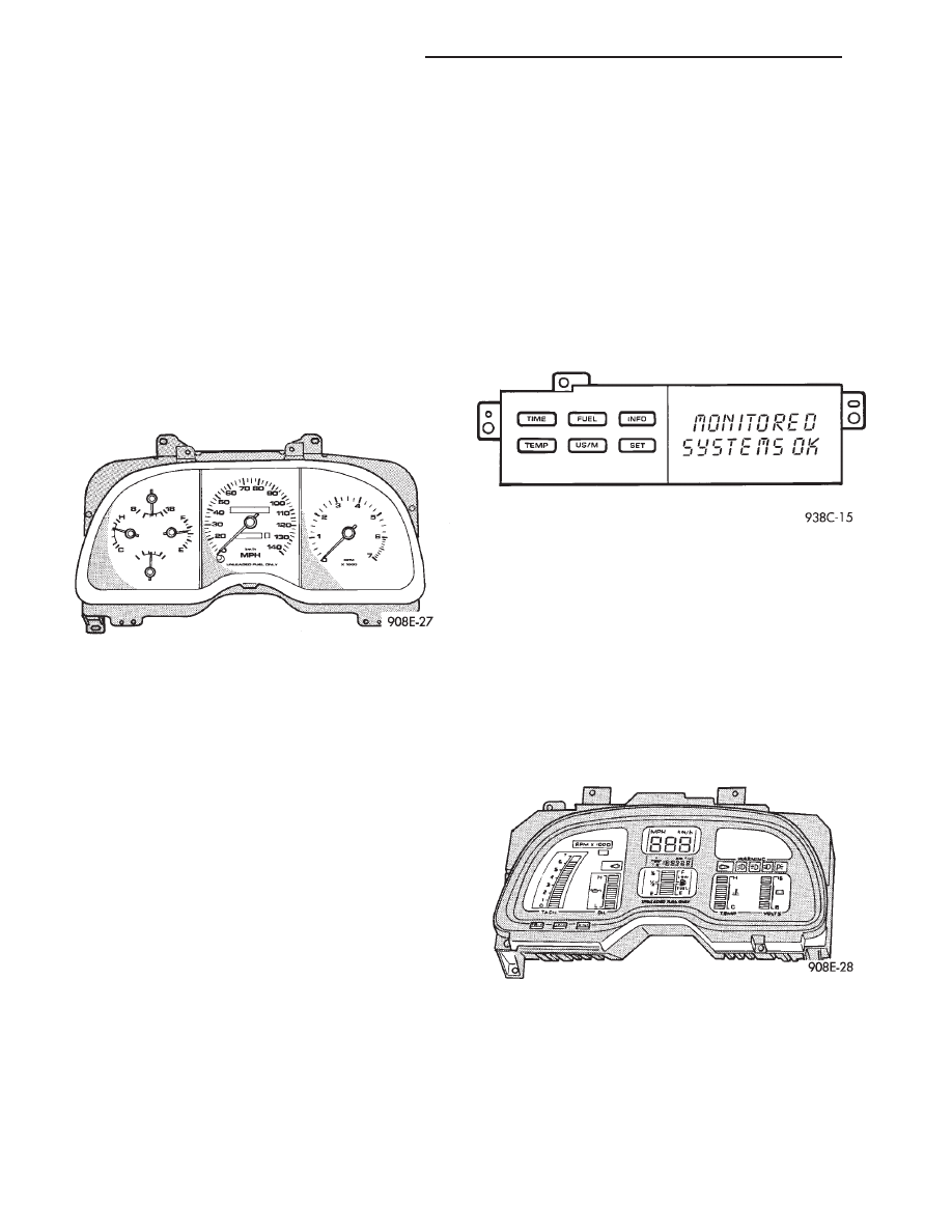
GLOVE BOX/ASH RECEIVER ASSEMBLY
REPLACEMENT
(1) Disconnect battery negative cable and isolate
or remove fuse #13 prior to removing switch or wires
may short to ground.
(2) Remove center support cover/floor console as
necessary.
(3) Disconnect glovebox/Ash receiver wiring con-
nectors (Fig. 39).
(4) Remove ten screws around edge of glovebox/ash
receiver assembly.
(5) Remove glovebox/ash receiver module from in-
strument panel.
(6) For installation reverse above procedures.
Fig. 37 Headlamp and Accessory Switch
Fig. 38 Body Controller Location
Ä
INSTRUMENT PANEL AND GAUGES
8E - 39
GLOVE BOX LAMP/SWITCH REPLACEMENT
(1) Disconnect battery negative cable and isolate
or remove fuse #13 prior to removing switch or wires
may short to ground.
(2) Open glove box door. The lamp can be removed
without removing switch.
(3) Remove switch by squeezing retaining tabs
from behind switch and slide rearward. Disconnect
wiring connectors.
(4) Remove lamp/switch.
(5) For installation reverse above procedures.
CIGAR LIGHTER ASSEMBLY REPLACEMENT
(1) Remove four screws from ash receiver.
(2) Pull assembly rearward and disconnect wiring.
(3) Remove ash receiver and cigar lighter.
(4) For installation reverse above procedures.
FLOOR CONSOLE REPLACEMENT
(1) Open upper storage bin door (Fig. 40).
(2) Remove two screws attaching front wall of stor-
age bin to mounting bracket.
(3) Remove console and drawer.
(4) Remove two screws attaching mounting bracket
to lower instrument panel.
(5) Remove mounting bracket.
(6) For installation reverse above procedures.
INSTRUMENT PANEL TOP COVER
REPLACEMENT
(1) Remove panel top cover by, pushing forward
and prying up, using a straight edge to assist in the
removal.
(2) For installation: align top cover clips and push
cover into position.
(3) Pull cover rearward for good fit.
INSTRUMENT PANEL ASSEMBLY
REPLACEMENT
CAUTION: Disconnect negative battery cable, in en-
gine
compartment,
before
servicing
instrument
panel.
(1) Remove left instrument panel silencer.
(2) Remove right and left cowl side and scuff plate
trim molding by removing five screws per side.
(3) Remove right and left A-pillar trim moldings
by removing two push-pin fasteners per side and dis-
engaging from clip at B-pillar trim.
Fig. 39 Glovebox/Ash Receiver Assembly
Fig. 40 Floor Console
8E - 40
INSTRUMENT PANEL AND GAUGES
Ä
(4) Remove panel top cover by pushing forward
and prying up, using a straight edge to assist in the
removal.
(5) Disconnect bulkhead connector at brace under
instrument panel at left side.
(6) Remove glovebox/ash receiver module and right
instrument panel silencer.
(7) Remove center panel support brace and air bag
diagnostic module assembly.
(8) Disconnect wiring to airbag module.
(9) Remove upper and lower cluster bezels.
(10) Remove steering column cover.
(11) Remove steering column mounting nuts and
lower steering column.
(12) Unhook shift indicator cable eyelet from steer-
ing column actuator.
(13) Unlatch lock tab in shift indicator column in-
sert and squeeze legs together to remove from steer-
ing column.
(14) Remove cluster assembly while guiding trans-
mission range indicator guide tube through access
hole in the base panel.
(15) Remove instrument panel steering column
opening support/hood release handle assembly.
(16) Remove two steering column upper studs and
loosen side cowl tie-down bolts.
(17) Remove steering column tilt lever.
(18) Remove upper and lower lock housing shroud.
(19) Remove lower fixed shroud.
(20) Remove upper fixed shroud (snaps in place).
(21) Disconnect airbag pigtail, ignition switch and
halo light/key buzzer switch wiring.
(22) Disconnect Multi-function switch by loosening
connector jack screw and pulling connector from
switch.
(23) Disconnect airbag pigtail from wiring trough
housing by pulling two push fasteners.
(24) Remove wiring trough from steering column.
(25) Remove defroster ducts.
(26) Remove five screws along fence line and roll
panel down, attach a hook to hold in position.
(27) Open hood and remove plenum grill.
(28) Disconnect washer bottle, resistor block and
under hood lamp wiring. Washer bottle must be re-
moved to gain access.
(29) Remove grommet and pull plenum wiring into
vehicle through plenum panel.
(30) Disconnect right demister hose from instru-
ment panel.
(31) Disconnect antenna cable.
(32) Disconnect right and left 25 way body wiring
connectors.
(33) Disconnect A/C heater control cables, wiring
connectors and vacuum harness.
(34) Remove right side panel ground wire.
(35) Disconnect body controller wiring.
(36) Remove instrument panel assembly from vehi-
cle.
(37) For installation reverse above procedures.
INTERIOR LAMP REPLACEMENT
The reading, overhead console and door lamps op-
erate when the doors are open or headlamp switch is
placed in courtesy position. Front overhead lamps re-
fer to Group 8C, Overhead Console.
TRUNK LAMP
The lamp has easily accessible without removing
components.
DOOR LAMP
Pry along the forward edge of the lens and pivot
lens out of the door trim panel. Remove lamp. To re-
move lamp housing, remove door trim panel. Refer to
Group 23, Body. Disconnect all wiring. Remove
screws, if so equipped securing lamp housing to trim
panel, and replace housing.
C—PILLAR READING/COURTESY LAMP
Pry along the rearward edge of the lamp and pivot
lamp out from quarter trim panel. Disconnect wiring
and remove lamp cover. Replace lamp.
The lamp operates when the doors are open or the
headlamp switch is turned to the courtesy mode. The
lamp will function as a reading lamp when the doors
are closed and the button switch on the lamp is de-
pressed.
ROOF RAIL READING
Pry along the bottom edge of the lens and pivot
lens out. Replace lamp. To remove the lamp, remove
the screw which retains the coat hook. Remove the
garnish molding. Disconnect the wiring harness. Re-
move the two clips which retain the lamp to the
molding. Replace lamp. The lamp operates like the
C-pillar reading/courtesy lamp.
Ä
INSTRUMENT PANEL AND GAUGES
8E - 41
AG AND AJ BODIES
INDEX
page
page
Cigar Lighter Removal
. . . . . . . . . . . . . . . . . . . . . 55
Cluster and Gauge Service and Testing
. . . . . . . 43
Electronic Cluster
. . . . . . . . . . . . . . . . . . . . . . . . 50
Electronic Vehicle Information Center (EVIC)
. . . . 42
Engine Compartment Node
. . . . . . . . . . . . . . . . . 55
Gauges
. . . . . . . . . . . . . . . . . . . . . . . . . . . . . . . . 44
General Information
. . . . . . . . . . . . . . . . . . . . . . . 42
Instrument Panel Roll Down Procedure
. . . . . . . . 56
Interior Lamp Removal
. . . . . . . . . . . . . . . . . . . . 57
Mechanical/Electronic Cluster Removal
. . . . . . . . 43
Switch and Panel Component Service
. . . . . . . . . 51
Switch Pod Assembly Removal
. . . . . . . . . . . . . . 43
GENERAL INFORMATION
CONVENTIONAL INSTRUMENT CLUSTER
The conventional instrument cluster incorporates
magnetic type gauges (Fig. 1).
The readings are only accurate when the ignition
switch is in the ON position.
TACHOMETER DRIVE MODULE
The tachometer drive module is an electronic mod-
ule used to drive a magnetic tachometer in a conven-
tional instrument cluster.
MESSAGE CENTER
The message center provides the driver with infor-
mation in addition to the standard vehicle instru-
mentation. A bezel will light up with door ajar,
washer fluid, deck ajar and alarm set information.
For vehicles without message center a plain bezel is
used.
ELECTRONIC VEHICLE INFORMATION CENTER
(EVIC)
The Electronic Vehicle Information Center is a
computer controlled warning system which, monitors
various sensors used on the vehicle. The system sup-
plements the warning indicators in the instrument
cluster. Visual warning messages are displayed by a
digital display (Fig. 2). Refer to Group 8C, Overhead
Console.
ELECTRONIC INSTRUMENT CLUSTER
The electronic instrument cluster uses vacuum flu-
orescent displays to display:
• Oil pressure
• System voltage
• Engine temperature
• Fuel level
• Speedometer and tachometer readings as well as
all warning indicators. The electronic cluster is eas-
ily distinguished from the conventional cluster by its
digital and linear display (Fig. 3.
ELECTRONIC CLUSTER DIMMING
The electronic cluster display is dimmed from day-
time to nighttime intensity when the head]lamp
switch is turned on. This intensity can be controlled
using the headlamp switch sliding rheostat.
An additional detent on the headlamp switch rheo-
stat will allow daytime intensity while driving with
headlamps ON in daytime.
Fig. 1 Conventional Instrument Cluster
Fig. 2 EVIC
Fig. 3 Electronic Instrument Cluster
8E - 42
INSTRUMENT PANEL AND GAUGES
Ä
Нет комментариевНе стесняйтесь поделиться с нами вашим ценным мнением.
Текст