Chrysler Le Baron, Dodge Dynasty, Plymouth Acclaim. Manual — part 308
ELECTRONIC DIGITAL CLOCK
The electronic digital clock is in the radio. The
clock and radio each use the display panel built into
the radio. A digital readout indicates the time in
hours and minutes whenever the ignition switch is in
the ON or ACC position.
When the ignition switch is in the ON or OFF po-
sition, or when the radio frequency is being dis-
played, time keeping is accurately maintained.
The procedure for setting the clock varies slightly
with each radio. The correct procedure is described
under the individual radio operating instructions re-
ferred to in the Owner’s manual supplied with the
vehicle.
WARNING LAMPS
The AG & AJ Body instrument clusters have warn-
ing lamps or indicators with the electronic cluster for
six different systems. These include low oil pressure,
check gauges, brake system, air bag, seat belt, mal-
function indicator (check engine) lamp.
CLUSTER AND GAUGE SERVICE AND TESTING
CAUTION: Disconnect negative battery cable, in en-
gine
compartment,
before
servicing
instrument
panel. When power is required for test purposes,
reconnect battery cable for test only.
Disconnect negative battery cable after test and be-
fore continuing service procedures.
It is not necessary to remove instrument cluster
from vehicle for gauge replacement.
Gauges must be pulled straight out, when remov-
ing or pins may be damaged.
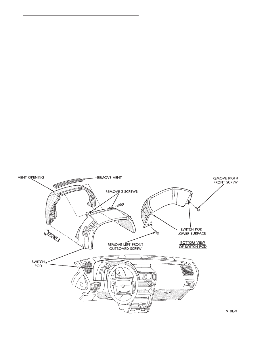
SWITCH POD ASSEMBLY REMOVAL
(1) Disconnect negative battery cable.
(2) Pry up edge of panel vent grille, using a
straight flat edge tool to disengage clips, then re-
move grille (Fig. 4).
(3) Remove two screws located under panel vent
grille.
(4) Remove two screws underneath switch POD as-
sembly.
(5) With tilt steering adjust steering wheel to the
lowest setting.
(6) Pull switch module rearward to remove module
and disconnect all wire connections.
(7) For
Installation
reverse
above
procedures.
Tighten all screws to 2 N
Im (20 in. lbs.) torque.
MECHANICAL/ELECTRONIC CLUSTER REMOVAL
CLUSTER MASK AND LENS REMOVAL
(1) Remove switch pod assembly (Fig. 4).
(2) Remove tilt column lever if equipped.
(3) Remove steering column trim cover.
Fig. 4 Switch POD Assembly
Ä
INSTRUMENT PANEL AND GAUGES
8E - 43

(4) Remove six screws holding the cluster mask
and lens assembly.
(5) Pull cluster mask and lens rearward to remove
(Fig. 5 and 6).
(6) For installation reverse above procedures.
CLUSTER ASSEMBLY REMOVAL
(1) Disconnect battery to assure no Air Bag Sys-
tem fault codes are stored.
(2) Remove switch pod assembly.
(3) Unscrew tilt column lever if equipped.
(4) Remove steering column trim cover.
(5) Remove attaching screws on cluster and pull
cluster rearward.
(6) Tilt cluster to disconnect wiring connections
and turbo gauge hose if equipped, then remove clus-
ter.
(7) For installation reverse above procedures.
GAUGES
MULTIPLE GAUGE INOPERATIVE
Volt, speedometer, tachometer and other gauges
appear to malfunction:
(1) Remove cluster
(2) Check for ignition voltage at cavity 9 of the red
cluster connector and ground. If no voltage, repair as
necessary (Fig. 7).
(3) Check for ground continuity between cavity 14
of the red cluster connector and ground. If no ground,
repair as necessary.
(4) If OK and pins or connectors are not distorted,
replace printed circuit board.
(5) Install cluster.
GAUGE CALIBRATION/INOPERATIVE
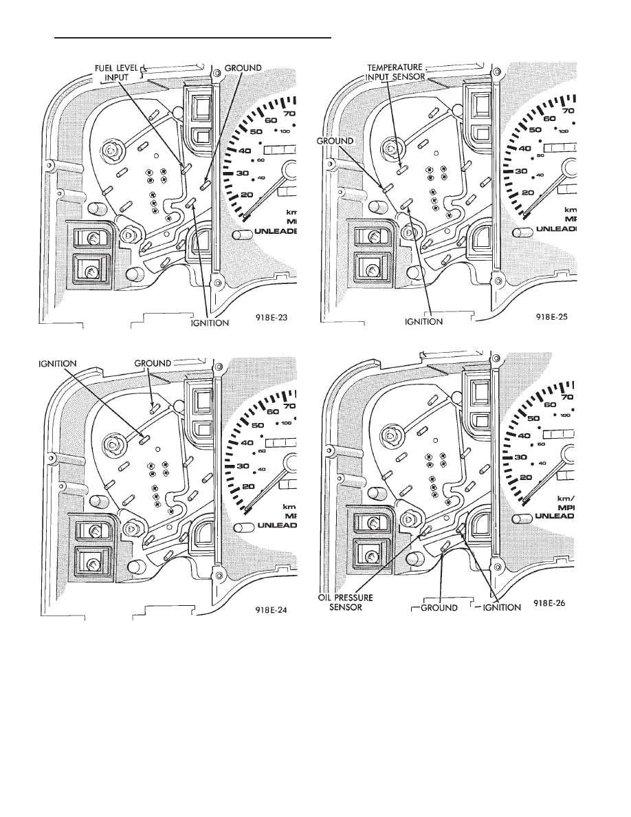
(1) Remove gauge in question (Fig. 8 through 11).
(2) With the ignition key ON, check for ignition
voltage at ignition pin of gauge and ground. Check
ground pin of gauge for continuity to ground.
(a) If no voltage or ground, check at cluster red
connector pin 9 for ignition voltage and pin 14 for
ground.
(b) If no voltage or ground, repair as necessary.
Refer to 8W, Wiring Diagrams.
(c) If there is voltage or ground, check cluster for
distorted terminals. If terminals are OK, replace
printed circuit board.
Fig. 5 Cluster Mask and Lens
Fig. 6 Cluster with Mask Removed
Fig. 7 Conventional Cluster Connectors
8E - 44
INSTRUMENT PANEL AND GAUGES
Ä
(3) When testing temperature and oil pressure
gauge, allow the engine to run until the vehicle
reaches a normal operating temperature. Turn igni-
tion OFF, and remove gauge from cluster.
(a) Testing oil pressure gauge, engine needs to
be running.
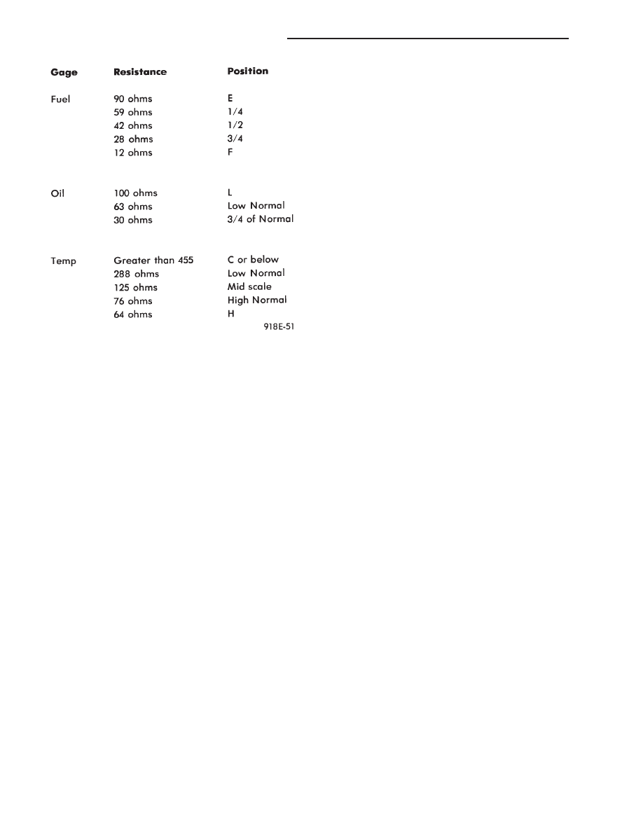
(b) Measure and record the resistance between
sending unit pin and ground pin of the gauge in
question. Refer to Gauge Resistance (Fig. 12).
(c) When checking temperature and oil pressure
gauges, it is important to have the same engine
temperature and engine speed when noting gauge
position. Therefore, time between noting gauge po-
sition and sending unit measuring should be kept
to a minimum.
(d) If resistance and gauge position are not sim-
ilar, replace gauge.
(e) If OK, measure the resistance between the
sending unit pin in question and the ground pin at
the cluster wire harness connectors.
Fig. 8 Fuel Gauge Pins
Fig. 9 Voltmeter Pins
Fig. 10 Temperature Gauge Pins
Fig. 11 Oil Pressure Gauge Pins
Ä
INSTRUMENT PANEL AND GAUGES
8E - 45
(f) If there is a difference in readings, check
printed circuit board for contact to cluster connec-
tors.
(g) If OK and contacts are not distorted, replace
printed circuit board.
(h) If everything checks out OK, refer to Sending
Unit Test.
(4) The Gauge Resistance Chart (Fig. 12), is gen-
eral guidelines for checking the gauge position
against the sending unit resistance. Because of only
a few specific points of gauge position versus sending
unit resistance, a good estimate is needed when the
resistance falls between graduations. Even when the
resistance corresponds to graduations, the gauge has
a tolerance of
6 4 ohms.
Volt gauge: The calibration dot on the volt gauge
corresponds to 13 volts between the gauge ignition
and ground pins. If voltage varies from this, estimate
proper gauge position with input voltage.
TACHOMETER AND TURBO GAUGE REMOVAL
(1) Remove switch pod assembly.
(2) Remove steering column trim cover.
(3) Remove cluster mask and lens assembly.
(4) Remove screws attaching tachometer to cluster
housing.
(5) Pull tachometer rearward to remove.
(6) Disconnect turbo gauge hose. If turbo hose can-
not be disconnected, remove cluster.
(7) For installation reverse above procedures.
TACHOMETER CIRCUIT TESTING
(1) Remove cluster.
(2) Check for battery voltage at cavity 8 of the in-
strument cluster red connector (Fig.6).
(3) With the ignition in the ON position, check for
battery voltage at cavity 9 of the instrument cluster
red connector.
(4) Check cavity 14 of the instrument cluster red
connector for continuity to ground.
(5) Check for tachometer signal from the power-
train control module by connecting an AC DIGITAL
VOLTMETER to cavity 6 of the instrument cluster
black connector and ground. A reading of at least 1.0
volt should be present with the engine running (Fig.
7).
(a) If voltage is within specification, go to step 7.
(b) If voltage is NOT within specification, per-
form steps 6.
(6) If there is less than 1.0 volt at cavity 6, check
for continuity between cavity 6 and pin 43 of the
powertrain control module connector.
(a) If continuity is OK, between cavity 6 and pin
43 of the powertrain control module connector, re-
place the powertrain control module.
(b) No continuity check the connectors for dam-
aged pins or terminal push outs or defective wire.
(7) If all tests performed test good replace the ta-
chometer drive module.
(8) If the tachometer continues to be inoperative,
replace the tachometer assembly.
VOLTMETER, TEMPERATURE GAUGE, OIL
PRESSURE GAUGE AND FUEL GAUGE
ASSEMBLY—REMOVAL
(1) Remove pod switch assembly.
(2) Remove steering column trim cover.
(3) Remove cluster mask and lens assembly.
(4) Remove screws attaching gauge assembly to
cluster.
(5) Pull rearward to remove gauge assembly.
(6) For installation reverse above procedures.
SENDING UNIT TEST
It is not necessary to remove instrument clus-
ter from vehicle for gauge replacement.
When removing gauge assemblies from cluster,
gauge must be pulled straight out, not twisted, or
damage to gauge pin may result.
When a problem occurs with a cluster gauge, be-
fore disassembling the cluster to check the gauge,
check for a defective sending unit or wiring.
(1) Sending units and wiring can be checked by
grounding the connector leads, at the sending unit,
in the vehicle.
(2) With the ignition in the ON position; a
grounded input will cause the oil, fuel or tempera-
ture gauge to read at or above maximum.
Fig. 12 Gauge Resistance
8E - 46
INSTRUMENT PANEL AND GAUGES
Ä
Нет комментариевНе стесняйтесь поделиться с нами вашим ценным мнением.
Текст