Chrysler Le Baron, Dodge Dynasty, Plymouth Acclaim. Manual — part 342

PROBLEM
Headlamp door or doors fit poorly, rattle, or bang
when coming open or closed.
CHECK:
• Headlamp door fascia mounting bracket or adjust-
able stops for improper alignment.
• Headlamp door pivot brackets or door/crank lateral
adjustment for improperly aligned collar.
• For missing or worn pivot bushings.
• For defective motor.
HEADLAMP DOOR—AC-BODY
REMOVAL (FIG. 2)
(1) Remove the grill. Refer to Group 23, Body.
(2) Remove the front bumper assembly. Refer to
Group 23, Body.
(3) Loosen and separate the grille opening panel
from the front fender on the side of the vehicle af-
fected. Refer to Group 23, Body.
(4) Compress torsion bar retainer clip tabs to-
gether and slide the retainer toward the center of the
vehicle. Separate the torsion bar from the door crank
on the side of the vehicle affected.
(5) Remove headlamp door side trim covers and
lower trim covers.
(6) Remove outer pivot screw, door crank screw,
and loosen the door (lateral) adjustment collar.
(7) Remove the door crank from the door and ad-
justment collar.
(8) Lower the door from under the grille opening
panel and remove the door from the vehicle.
INSTALLATION
Reverse the preceding operation.
CONCEALED HEADLAMP MOTOR—AC-BODY
REMOVAL (FIG. 2)
(l) Remove the grille. Refer to Group 23, Body.
(2) Compress torsion bar retainers and slide them
toward the center of the vehicle. Separate the torsion
bar from the door cranks.
(3) Disconnect the headlamp door drive motor wire
connector. Remove three motor attaching bolts and
separate the drive motor and torsion bar from the ve-
hicle.
INSTALLATION
Reverse the preceding operation.
HEADLAMP DOOR—AY BODY
REMOVAL
(1) Turn headlight switch ON.
Fig. 2 Concealed headlamps—AC-body
Ä
LAMPS
8L - 29
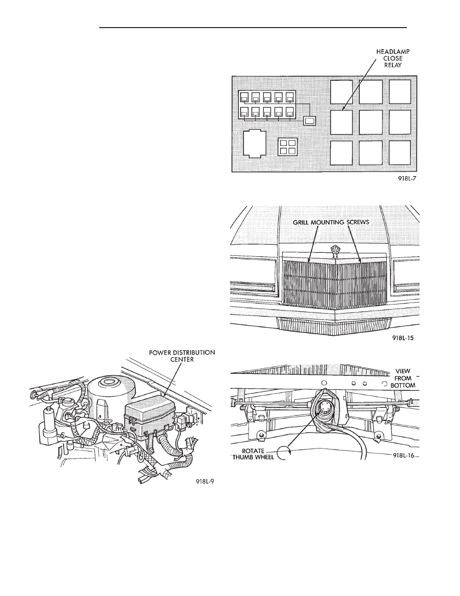
(2) Open hood and locate Power Distribution Cen-
ter forward of the left suspension tower (Fig. 3).
(3) Remove cover from the center and pull the
Headlamp Close Relay (Fig. 4) to keep the headlamp
doors from closing.
(4) Turn headlight switch OFF.
(5) Remove two grill mounting screws and remove
grill assembly (Fig. 5).
(6) Spring tension must be relieved from the head-
lamp doors before removing headlamp motor torsion
bar clips. Locate the thumb wheel on bottom of head-
lamp motor (Fig. 6). Rotate thumb wheel approxi-
mately six to seven turns clockwise to relieve all
tension.
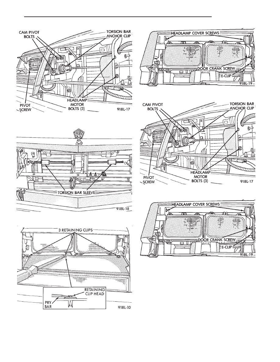
(7) Remove torsion bar anchor clip (Fig. 7).
(8) Slide torsion bar sleeve over the torsion bar
(Fig. 8).
(9) Remove three clips retaining turn signal lamp
shield to body (Fig. 9), and remove shield.
(10) Remove two screws retaining headlamp cover
to headlamp cover bracket (Fig. 10).
(11) Remove outer headlamp.
(12) Remove outer pivot screw (Fig. 11).
(13) Remove E-clip and door crank screw (Fig. 12).
(14) Remove three bolts retaining cam pivot to
body and remove cam pivot (Fig. 11).
(15) Remove Headlamp door assembly.
INSTALLATION
Reverse the preceding operation. Before installing
torsion bar clips, the holes in the torsion bars, tor-
sion bar sleeves and headlamp door cam pivots must
be in alignment. Refer to Aligning Headlamp Doors.
HEADLAMP DRIVE MOTOR—AY BODY
REMOVAL
(1) Open headlamp doors. Refer to Headlamp Door
paragraph for instructions.
(2) Remove grill mounting screws and remove grill
assembly (Fig. 5).
(3) Spring tension must be relieved from headlamp
doors before removing the headlamp motor torsion
bar clips. Locate the thumb wheel on bottom of the
headlamp motor (Fig. 6). Rotate thumb wheel ap-
proximately six to seven turns (clockwise) to relieve
all tension.
(4) Remove both torsion bar anchor clips (Fig. 7).
(5) Slide torsion bar sleeves over the torsion bar
(Fig. 8).
Fig. 3 Power Distribution Center
Fig. 4 Headlamp Close Relay
Fig. 5 Grill
Fig. 6 Headlamp Motor—Bottom View
8L - 30
LAMPS
Ä
(6) Disconnect wire connector from motor.
(7) Remove motor mounting bolts (Fig. 11).
(8) Slide torsion bar through the headlamp motor
(Fig. 13) and remove headlamp motor.
INSTALLATION
Reverse the preceding operation. Before installing
torsion bar clips, the holes in the torsion bars, tor-
sion bar sleeves and headlamp door cam pivots must
be in alignment.
HEADLAMP DOOR ALIGNMENT
Door stop adjustment screws, and a movable cam
pivot are used to adjust and align the headlamp
doors.
Fig. 9 Front Turn Signal Lamp Shield
Fig. 10 Headlamp Cover/Cover Pivot Bracket
Fig. 7 Torsion Bar Anchor Clips
Fig. 8 Torsion Bar Sleeves
Fig. 11 Outer Pivot Screw
Fig. 12 Headlamp Pivot E-Clip and Crank Screw
Ä
LAMPS
8L - 31

Loosening the cam pivot bolts (Fig. 14) will allow
an up/down or in/out adjustment of the headlamp
doors.
The stop screws (Fig. 14) are also used to achieve
proper tolerances.
Fig. 13 Headlamp Motor
Fig. 14 Cam Pivot Adjustment
8L - 32
LAMPS
Ä
Нет комментариевНе стесняйтесь поделиться с нами вашим ценным мнением.
Текст