Chrysler Le Baron, Dodge Dynasty, Plymouth Acclaim. Manual — part 341

EXTERIOR LAMP SYSTEMS
INDEX
page
page
Daytime Running Lamp—Canada Only
. . . . . . . . . . . . . . 26
Lamp Outage Module—All Except AA-Body
. . . . . . . . . . . . . . . . . . . . . 25
. . . . . . . . . . . . . . . . . . . . . . . . . 25
LAMP OUTAGE SYSTEM
Diagnostics and component relationships for AC,
AG, AJ or AY-Bodies can be found in the Body Di-
agnostic Procedures Manual, Electronic Vehicle In-
formation Center (EVIC) section.
For circuit and component locations on AA-body,
refer to the Wiring Diagrams Manual.
LAMP OUTAGE MODULE—ALL EXCEPT AA-BODY
REMOVAL
(1) Remove battery negative cable.
(2) Remove the glove box assembly. Refer to Group
8E, Instrument Panel.
(3) Disconnect the wire connector from the lamp
outage module.
(4) Remove lamp outage module attaching screw
and remove the module from the vehicle (Figs. 1, 2
or 3).
INSTALLATION
Reverse the preceding operation.
LAMP OUTAGE MODULE—AA-BODY
REMOVAL (FIG. 1)
(1) Remove battery negative cable
(2) Disconnect the wire connectors from the lamp
outage module.
(3) Remove screws or clip holding lamp outage
module to instrument panel above glove compart-
ment (Fig. 1, 2 or 3).
(4) Separate lamp outage module from vehicle.
INSTALLATION
Reverse the preceding operation.
DAYTIME RUNNING LAMP—CANADA ONLY
DIAGNOSIS
For circuit and component locations refer to the
Wiring Diagrams manual.
REMOVAL (FIG. 4)
(1) Remove the left front inner fender shield, if
equipped, and disconnect the wire connector from the
day time running lamp module.
(2) Remove daytime running lamp module attach-
ing screws and separate the module from the inner
fender support.
INSTALLATION
Reverse the preceding operation.
Fig. 1 Lamp Outage Module—AA-Body
Fig. 2 Lamp Outage Module—AG and AJ-Body
Ä
LAMPS
8L - 25

HEADLAMP TIME DELAY SYSTEM
SYSTEM OPERATION
The Body Controller controls the Headlamp Time
Delay system, if equipped.
OPERATION:
By turning off the ignition switch first then off the
headlamp switch, the Body Controller will allow the
headlamps to remain ON for 60 seconds before they
automatically turn off and the headlamp doors close.
DIAGNOSIS
Refer to the Pre-diagnostic Test section of the ap-
propriate Body Diagnostic Procedures service man-
ual.
Fig. 3 Lamp Outage Module—AC and AY-Body
Fig. 4 Daytime Running Lamp Module—Canada
Only
8L - 26
LAMPS
Ä

CONCEALED HEADLAMPS
INDEX
page
page
Concealed Headlamp Motor—AC-Body
. . . . . . . . . . . . . . . . . . . . . 27
. . . . . . . . . . . . . . . . . . . . . . . 27
. . . . . . . . . . . . . . . . . 29
. . . . . . . . . . . . . . . . . 29
GENERAL INFORMATION
For proper operation of the Concealed Headlamp
System, refer to the Owner’s Manual provided with
the vehicle.
The Concealed Headlamps are controlled by the Body
Controller (Fig. 1). Refer to Group 8E, Instrument
Panel for service procedures. The Body Controller re-
ceives input information from the ignition switch, head-
lamp switch, and the headlamp dimmer switch.
The Body Controller also controls the headlamp doors
when the Passing Lights (manually flashing bright
lights) are used. With the headlamp switch turned off,
actuating the headlamp dimmer switch will signal the
Body Controller to open the headlamp doors. The oper-
ator then has two seconds to flash the bright lights be-
fore the Body Controller closes the headlamp doors.
Holding the headlamp dimmer switch in the engaged
position will signal the Body Controller to keep the
headlamp doors open until the dimmer switch is re-
leased. Actuating the headlamp dimmer switch with the
parking lamps ON signals the Body Controller to open
the headlamp doors and keep them open until the head-
lamp switch is turned off.
AY and AC vehicles use a single motor, centrally
located behind the radiator grille, and linked to the
headlamp doors by a torsion bar. Refer to Service
Procedures for more information.
The headlamp door drive motors are equipped with
a manual override hand wheel to open or close the
headlamp doors if a failure should occur or servicing
is required. Access to the handwheel can be gained
through a flap covered hole in the sight shield be-
hind the bumper fascia, and under the hood. Several
revolutions of the handwheel may be required to
move the headlamp doors.
DIAGNOSTIC PROCEDURES
Before diagnosing a problem with the headlamp
doors, check for possible collision damage, binding,
improperly installed assemblies, or freezing weather
conditions.
When diagnosing an electrical problem, refer to:
• The Concealed Headlamps Electrical Diagnosis
chart in this section.
• The Wiring Diagrams Manual.
• The Headlamp Doors System section of the appro-
priate Body Diagnostic Procedures Manual.
PROBLEM
One headlamp door is inoperative when the head-
lamp switch is ON and the ignition switch is in the
RUN position. The other headlamp door operates
normally.
AC OR AY-VEHICLE BODY CHECK:
• Headlamp door pivot and crank for seizure.
• Headlamp torsion bar sleeve or clip for excessive
wear or breakage.
• Headlamp door crank for missing or broken screw.
• Headlamp torsion bar for disengagement or break-
age.
PROBLEM
Headlamp door operates erratically.
CHECK:
• For freezing weather conditions.
• For excessive effort to move headlamp door pivots.
• For corrosion or improperly aligned components.
• For stripped motor reduction gears.
• For defective body controller. Refer to the Con-
cealed Headlamp Electrical Diagnosis chart in this
section. Also refer to the Wiring Diagrams Manual
and Body Diagnostic Procedures Manual.
Fig. 1 Body Controller
Ä
LAMPS
8L - 27
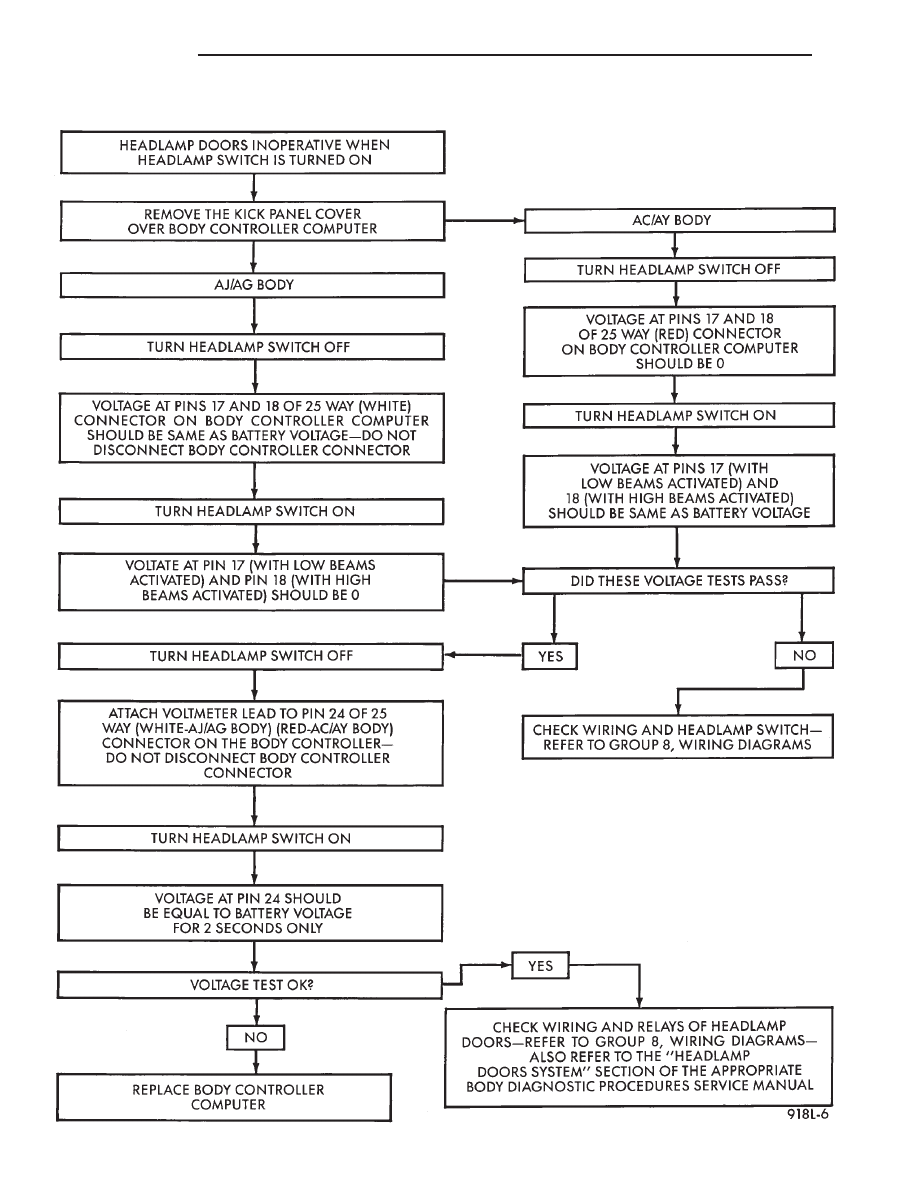
CONCEALED HEADLAMPS—ELECTRICAL DIAGNOSIS
8L - 28
LAMPS
Ä
Нет комментариевНе стесняйтесь поделиться с нами вашим ценным мнением.
Текст