Chrysler Le Baron, Dodge Dynasty, Plymouth Acclaim. Manual — part 153
hinge. If the welded half of the hinge must be bent to
align door, consult an authorized body repair facility.
REAR DOOR REMOVAL (FIG. 27)
(1) Remove B-pillar trim panel and disconnect all
wire connectors leading to door. Push wire harness
through access hole in B-pillar into hinge opening.
(2) Support door on a suitable lifting device.
(3) Drive bottom hinge pin upward and remove pin
from hinge.
(4) Drive top hinge pin downward and remove pin
from hinge.
(5) Separate door from vehicle.
REAR DOOR INSTALLATION
Reverse the preceding operation. The door should
not require re-alignment. If door does need align-
ment, refer to Rear Door Hinge Installation para-
graph in this section.
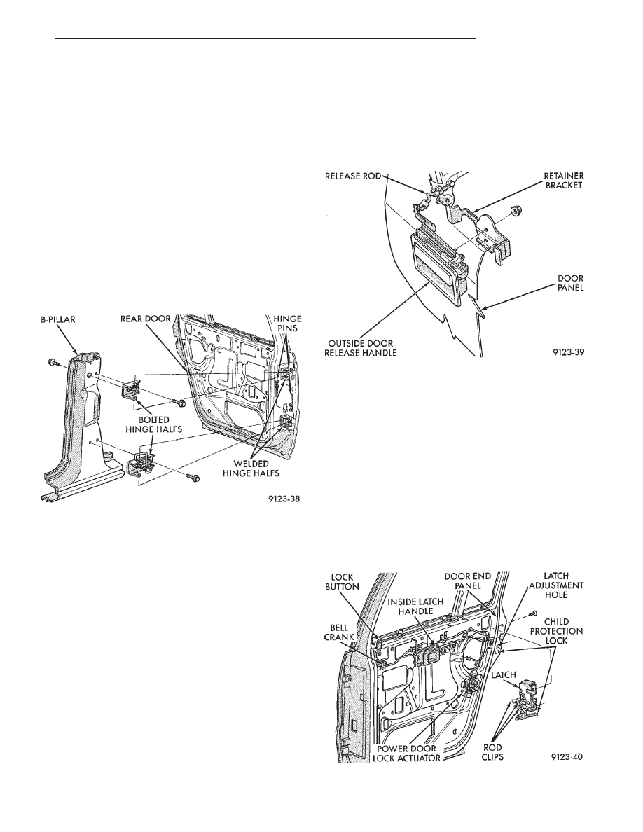
REAR DOOR HINGE REMOVAL (FIG. 27)
(1) To remove upper hinge bolted half, remove
B-pillar trim panel. To remove lower hinge bolted
half it is not necessary to remove B-pillar trim.
(2) Support rear door on a suitable lifting device.
(3) Drive out hinge pin on the effected hinge.
(4) Remove bolts holding hinge to B-pillar and sep-
arate hinge form vehicle.
REAR DOOR HINGE INSTALLATION
Reverse the preceding operation. Align door to
achieve 6 mm (0.240 in.) gap to all surrounding pan-
els and flush across gaps.
OUTSIDE REAR DOOR LATCH RELEASE HANDLE
REMOVAL (FIG. 28)
(1) Remove door trim panel, silencer pad, and wa-
ter shield.
(2) Raise door glass to full up position.
(3) Remove rear door speaker, if equipped.
(4) Disconnect latch release rod from door latch as-
sembly.
(5) Remove nuts holding outside door latch handle
to retainer bracket and separate bracket from door.
(6) Separate latch handle from door panel.
INSTALLATION
Reverse the preceding operation.
REAR DOOR LATCH
REMOVAL (FIG. 29)
(1) Remove door trim panel, silencer pad and wa-
ter shield.
(2) Raise door glass to full up position.
(3) Remove door speaker, if equipped.
(4) Disconnect all actuator rods from door latch as-
sembly.
(5) Remove screws holding door latch assembly to
inner door rear panel and separate from door.
INSTALLATION
Reverse the preceding operation.
Fig. 27 Rear Door Assembly
Fig. 28 Outside Rear Door Latch Release Handle
Fig. 29 Rear Door Latch Assembly
Ä
AA-BODY
23 - 21
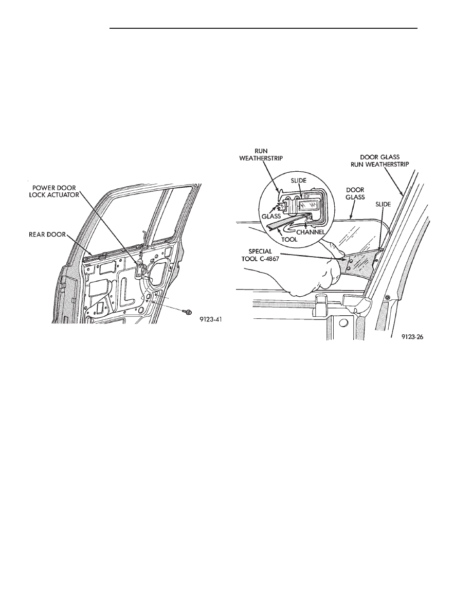
REAR POWER DOOR LOCK ACTUATOR
REMOVAL (FIG. 30)
(1) Remove door trim panel, silencer pad, and wa-
ter shield.
(2) Raise door glass to full up position.
(3) Remove door speaker, if equipped.
(4) Disconnect actuator rod from door latch assem-
bly.
(5) Remove screws holding power lock actuator to
inner door panel and separate from door.
INSTALLATION
Reverse the preceding operation.
REAR DOOR GLASS
REMOVAL (FIG. 31)
(1) Remove door trim panel, silencer pad, and wa-
ter shield.
(2) Position door glass half way up in door glass
opening.
(3) Pull upward firmly at the front upper corner of
glass to disengage lower glass guide from run chan-
nel.
(4) Insert door glass removal tool C-4867 between
the glass slide and division run channel retaining lip
at approximately 50 mm (2 in.) down from top rear-
ward corner of glass. Push handle of tool toward
glass to open channel. Pull forward on the glass to
separate the slide from the channel.
(5) Position glass inboard of the division channel.
Pivot top of glass rearward between division channel
and inner door panel.
(6) Separate regulator lift arm roller from glass lift
channel. Hold regulator lift arm outward and lift
glass upward.
(7) Remove door glass through opening at top of
door.
INSTALLATION
(1) Lower door glass into opening at top of door.
(2) Insert window regulator lift arm roller into
glass lift channel.
(3) Push top of glass rearward to snap top slide
into division run channel.
(4) Push downward at front of glass to snap bottom
slide into channel.
(5) Install water shield, silencer pad and trim
panel.
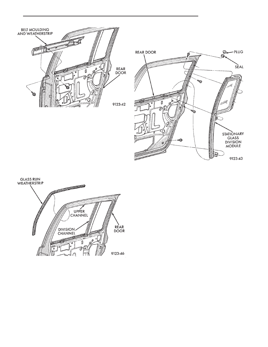
REAR DOOR BELT MOULDING AND
WEATHERSTRIP
BELT MOULDING AND WEATHERSTRIP
REMOVAL (FIG. 32)
(1) Remove trim panel, silencer pad, and water
shield.
(2) Remove door glass.
(3) Remove screws holding belt moulding and
weatherstrip to outer door panel and separate moul-
ding from door.
BELT MOULDING AND WEATHERSTRIP
INSTALLATION
Reverse the preceding operation.
REAR DOOR GLASS RUN WEATHERSTRIP
REMOVAL (FIG. 33)
(1) Remove door belt moulding and weatherstrip
assembly.
(2) Pull door glass run weatherstrip from forward
lower channel and upper door frame back to division
channel.
Fig. 30 Rear Power Lock Actuator
Fig. 31 Rear Door Glass
23 - 22
AA-BODY
Ä
(3) Separate glass run weatherstrip from door.
INSTALLATION
(1) Insert glass run weatherstrip into top of glass
opening upper channel. Align molded corner of
weatherstrip to upper front corner of glass opening.
(2) Push weatherstrip into upper rear corner of
door frame above division channel.
(3) Install door belt moulding and weatherstrip as-
sembly.
REAR DOOR GLASS STATIONARY GLASS MODULE
STATIONARY GLASS MODULE REMOVAL
(FIG. 34)
(1) Remove belt moulding and weatherstrip assem-
bly.
(2) Remove upper window opening moulding.
(3) Remove bolts and screws holding division chan-
nel and glass module to door assembly and separate
module from door frame.
(4) Remove module through opening at top of door.
STATIONARY GLASS MODULE INSTALLATION
Reverse the preceding operation. Use two sided ad-
hesive tape to secure module weatherstrip to inside
of door frame.
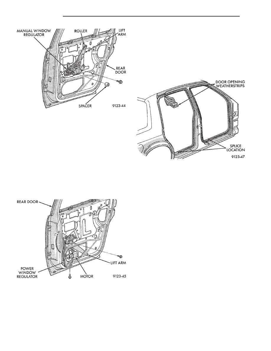
REAR DOOR WINDOW REGULATOR/MANUAL
MANUAL WINDOW REGULATOR REMOVAL
(FIG. 35)
(1) Remove trim panel, silencer pad, and water
shield.
(2) Position door glass 150 mm (6 in.) up into glass
opening. Pull upward firmly at front edge of glass to
disengage lower glass run guide from division chan-
nel.
(3) Remove bolts holding window regulator to in-
ner door panel.
(4) Slide roller from window lift channel.
(5) By hand, pull glass upward to 25 mm (1 in.)
from full up position. Using suitable tape, secure
door glass to upper window frame.
(6) Remove regulator assembly from door.
MANUAL WINDOW REGULATOR
INSTALLATION
Reverse the preceding operation.
REAR DOOR WINDOW REGULATOR/POWER
POWER WINDOW REGULATOR REMOVAL
(FIG. 36)
(1) Remove trim panel, silencer pad, and water
shield.
Fig. 32 Rear Door Belt Moulding and Weatherstrip
Fig. 33 Rear Door Glass Run Weatherstrip
Fig. 34 Rear Door Stationary Glass Module
Ä
AA-BODY
23 - 23
(2) Position door glass 150 mm (6 in.) up into glass
opening. Firmly pull upward at front edge of glass to
disengage lower glass run guide from division chan-
nel.
(3) Remove bolts holding window regulator to in-
ner door panel.
(4) Slide roller from window lift channel.
(5) By hand, pull glass upward to 25 mm (1 in.)
from full up position. Using suitable tape, secure
door glass to upper window frame.
(6) Remove regulator assembly from door.
POWER WINDOW REGULATOR INSTALLATION
Reverse the preceding operation.
DOOR OPENING WEATHERSTRIPS
FRONT OR REAR DOOR OPENING
WEATHERSTRIP REMOVAL (FIG. 37)
(1) Remove interior trim as necessary to gain ac-
cess to door opening weatherstrip.
(2) Pull weatherstrip from pinch flange around
door opening.
FRONT OR REAR DOOR OPENING
WEATHERSTRIP INSTALLATION
(1) Locate the middle to the weatherstrip at the
center of the upper pinch flange. Push weatherstrip
onto pinch flange at the top corner near the B-pillar.
(2) When the weatherstrip has been installed down
the door opening to the sill pinch flange, mate the
ends of the weatherstrip together and finish install-
ing.
BODY SIDE MOULDING AND APPLIQUE
STICK-ON BODY SIDE MOULDING REMOVAL
AND INSTALLATION (FIG. 38)
(1) Warm the effected stick-on moulding and body
metal to approximately 38°C (100°F) using a suitable
heat lamp or heat gun.
(2) Pull stick-on moulding from painted surface.
(3) Remove adhesive tape residue from painted
surface of vehicle.
(4) If moulding is to be reused, Remove tape resi-
due from moulding. Clean back of moulding with Mo-
par,
Super
Kleen
solvent
or
equivalent.
Wipe
moulding dry with lint free cloth. Apply new body
side moulding (two sided adhesive) tape to back of
moulding.
(5) Clean body surface with Mopar, Super Kleen
solvent or equivalent. Wipe surface dry with lint free
cloth.
(6) Apply a length of masking tape on the body,
parallel to the top edge of the moulding to use as a
guide, if necessary.
(7) Remove protective cover from tape on back of
moulding. Apply moulding to body below the mask-
ing tape guide.
(8) Remove masking tape guide and heat body and
moulding, see step one. Firmly press moulding to
body surface to assure adhesion.
Fig. 35 Rear Door Window Regulator—Manual
Fig. 36 Rear Door Window Regulator—Power
Fig. 37 Door Opening Weatherstrips
23 - 24
AA-BODY
Ä
Нет комментариевНе стесняйтесь поделиться с нами вашим ценным мнением.
Текст