Chrysler Le Baron, Dodge Dynasty, Plymouth Acclaim. Manual — part 152

FRONT DOOR SIDE VIEW MIRROR
REMOVAL (FIG. 16)
(1) Remove front door trim panel.
(2) Remove side view mirror remote adjusting
knob cover, if equipped.
(3) Remove screws holding mirror bezel to door
frame and separate bezel from door. Loosen set-screw
holding bezel to mirror adjuster cable, if equipped.
(4) Remove silencer seal from door frame behind
mirror bezel.
(5) Disconnect power mirror wire connector, if
equipped.
(6) Remove access hole cover.
(7) Remove nuts holding mirror to door frame and
separate mirror from door.
INSTALLATION
Reverse the preceding operation.
FRONT DOOR GLASS
REMOVAL (FIG. 17)
(1) Remove door trim panel, silencer pad, and wa-
ter shield.
(2) Position door glass half way up in door glass
opening.
(3) Insert door glass removal tool C-4867 between
the glass slide and channel retaining lip at approxi-
mately 50 mm (2 in.) down from top rearward corner
of glass. Push handle of tool toward glass to open
channel. Push downward at the front of the glass to
separate the slide from the channel.
(4) Insert door glass removal tool C-4867 between
the glass slide and channel retaining lip at approxi-
mately 50 mm (2 in.) up from bottom rearward cor-
ner of glass through opening in inner door panel.
Push handle of tool toward glass to open channel.
Pull upward at front of glass to separate the slide
from the channel. Do not allow upper slide to snap
bank into channel.
(5) Rotate front of glass downward and slide glass
forward to separate glass lift channel from regulator
lift arm roller.
(6) Remove door glass through opening at top of
door.
INSTALLATION
(1) Lower door glass into opening at top of door.
(2) Tip rear of glass downward and insert window
regulator lift arm roller into glass lift channel.
(3) Guide door glass into glass run weatherstrip at
front of door.
(4) Push top of glass rearward to snap top slide
into glass run channel.
(5) Push downward at front of glass to snap bottom
slide into glass run channel.
(6) Install water shield, silencer pad and trim
panel.
FRONT DOOR BELT MOULDING AND
WEATHERSTRIP
BELT MOULDING AND WEATHERSTRIP
REMOVAL (FIG. 18)
(1) Remove trim panel, silencer pad, and water
shield as necessary to gain access to belt moulding
attaching screws.
(2) Remove door glass.
(3) Remove screws holding belt moulding and
weatherstrip to outer door panel and separate moul-
ding from door.
BELT MOULDING AND WEATHERSTRIP
INSTALLATION
Reverse the preceding operation.
Fig. 16 Front Door Side View Mirror
Fig. 17 Front Door Glass
Ä
AA-BODY
23 - 17
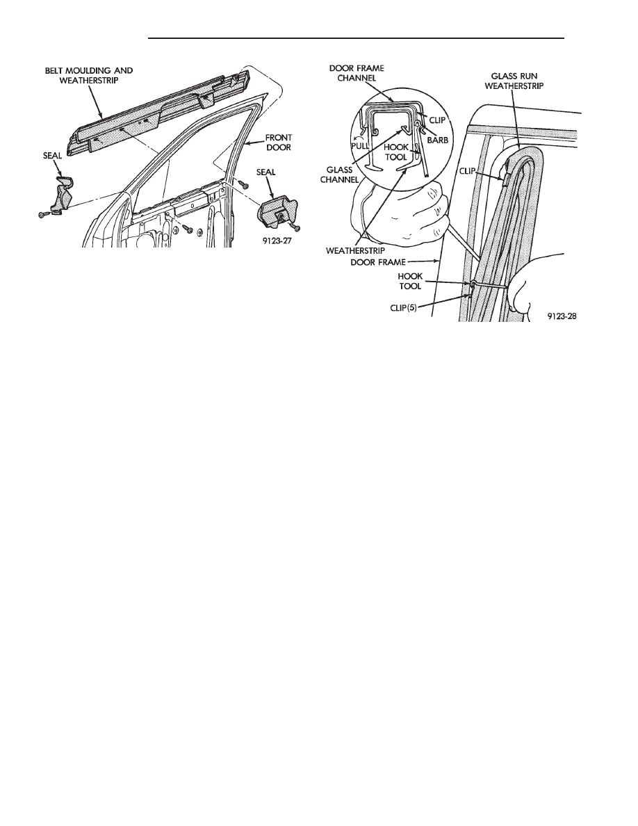
FRONT DOOR GLASS CHANNEL AND RUN
WEATHERSTRIP
GLASS CHANNEL AND RUN WEATHERSTRIP
REMOVAL (FIG. 19)
(1) Remove door belt moulding and weatherstrip
assembly.
(2) Remove front and rear door glass opening cor-
ner seals (Fig. 18)
(3) Pull door glass run weatherstrip from forward
lower channel and upper door frame back to rear up-
per corner of door frame.
(4) Separate weatherstrip from top of rear door
frame down to first clip. Using a suitable hook tool,
disengage clip barb from door frame channel. Pull
weatherstrip outward to disengage clip. Repeat this
procedure at each clip down the rear channel.
(5) Separate glass channel and run weatherstrip
from door.
GLASS CHANNEL AND RUN WEATHERSTRIP
INSTALLATION
(1) Insert glass run weatherstrip into top of glass
opening upper channel. Align molded corners of
weatherstrip to corners of glass opening.
(2) Push weatherstrip and glass run channel into
upper rear glass opening channel. Seat the top re-
taining clip by placing a fiber trim stick (C-4755)
over the clip attaching rivet inside the glass run
channel and push or tap firmly inward until clip
seats. Verify the alignment of the weatherstrip in
the top rear corner. Repeat this procedure on each
clip going down the run.
(3) Install glass opening corner seals.
(4) Install door belt moulding and weatherstrip as-
sembly.
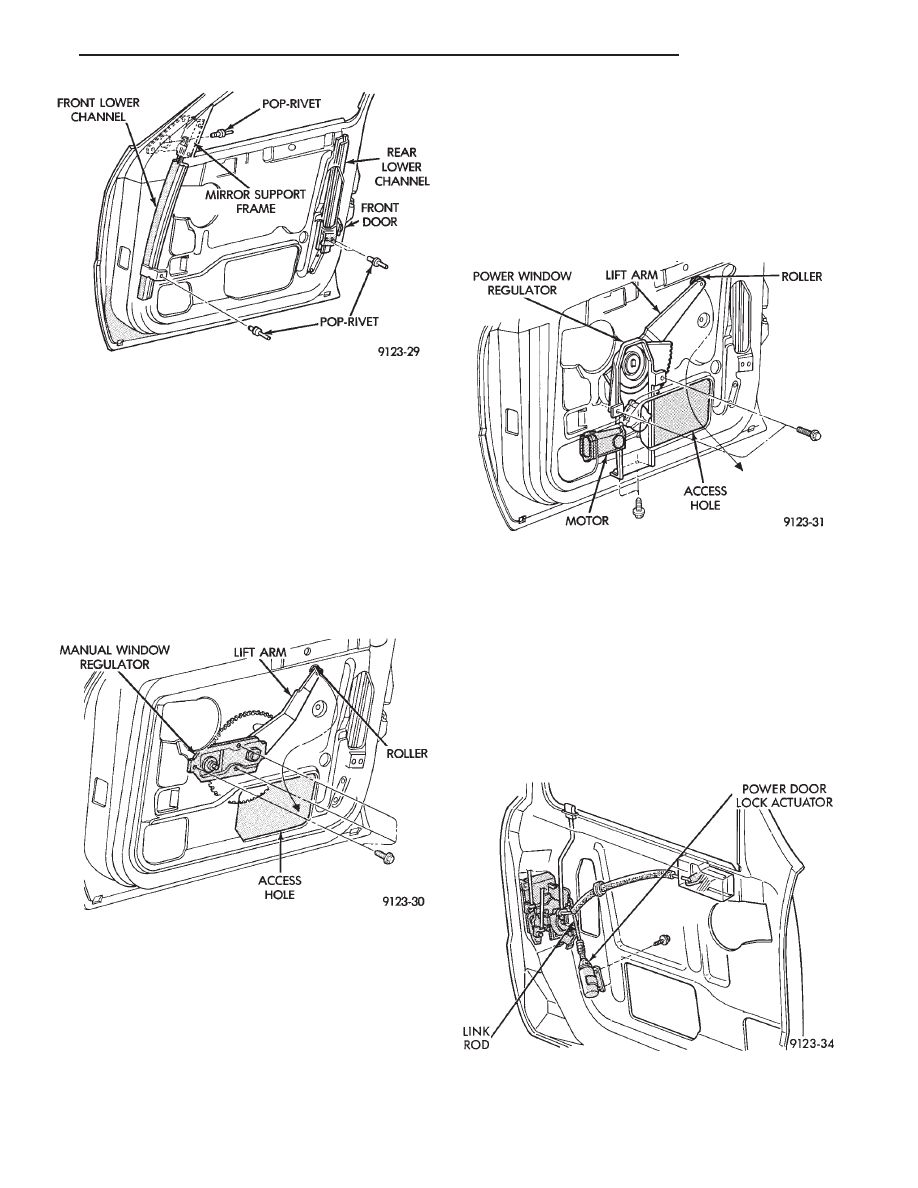
FRONT DOOR GLASS RUN LOWER CHANNEL
FRONT OR REAR LOWER CHANNEL REMOVAL
(FIG. 20)
(1) Remove door glass channel and run weather-
strip as necessary to gain access to lower channels
and attaching rivets.
(2) Drift punch rivet center expansion pins from
each pop-rivet fastener holding channel to door panel
or mirror support frame.
(3) Drill pop-rivet fasteners out of door panel or
mirror support frame and separate front or rear
channel from door.
FRONT OR REAR LOWER CHANNEL
INSTALLATION
(1) Install lower channel into at design location.
(2) Install pop-rivets using a suitable pop-rivet
gun.
(3) Install Glass channel and run weatherstrip.
(4) Install belt moulding and weatherstrip assem-
bly.
(5) Install door glass.
(6) Install window opening lower corner seals.
(7) Install door water shield silencer pad and trim
panel.
FRONT DOOR WINDOW REGULATOR/MANUAL
MANUAL WINDOW REGULATOR REMOVAL
(FIG. 21)
(1) Remove trim panel, silencer pad, and water
shield.
Fig. 18 Front Door Belt Moulding and Weatherstrip
Fig. 19 Front Door Glass Channel and Run
Weatherstrip
23 - 18
AA-BODY
Ä
(2) Raise glass to 25 mm (1 in.) from full up posi-
tion. Using suitable tape, secure door glass to upper
window frame.
(3) Remove bolts holding window regulator to in-
ner door panel.
(4) Slide roller from window lift channel. Rotate
regulator
to bring lift arm through access hole first.
(5) Remove regulator assembly from door.
MANUAL WINDOW REGULATOR
INSTALLATION
Reverse the preceding operation.
FRONT DOOR WINDOW REGULATOR/POWER
POWER WINDOW REGULATOR REMOVAL
(FIG. 22)
(1) Remove trim panel and water shield and con-
nect window switch to wire connector.
(2) Raise glass to 25 mm (1 in.) from full up posi-
tion. Using suitable tape, secure door glass to upper
window frame.
(3) Disconnect battery negative cable.
(4) Remove bolts holding window regulator to in-
ner door panel.
(5) Slide roller from window lift channel. Rotate
regulator
to bring lift arm through access hole first.
(6) Remove regulator assembly from door.
POWER WINDOW REGULATOR INSTALLATION
Reverse the preceding operation.
FRONT POWER DOOR LOCK ACTUATOR
REMOVAL (FIG. 23)
(1) Remove trim panel, silencer pad, and water
shield.
(2) Disconnect link rod from door latch.
(3) Remove bolts holding power door lock actuator
to inner door panel and separate actuator from door.
INSTALLATION
Reverse the preceding operation.
Fig. 20 Front Door Lower Channels
Fig. 21 Front Door Window Regulator—Manual
Fig. 22 Front Door Window Regulator—Power
Fig. 23 Front Power Door Lock Actuator
Ä
AA-BODY
23 - 19
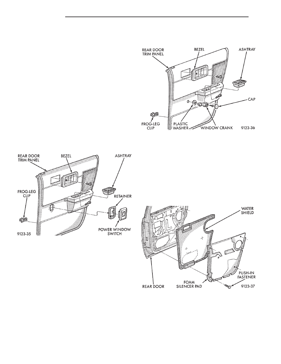
REAR DOOR TRIM PANEL
DOOR TRIM PANEL WITH POWER WINDOWS
REMOVAL (FIG. 24)
(1) Move glass to down position.
(2) Disconnect battery negative cable.
(3) Remove screw holding latch release handle be-
zel to door. Slide bezel forward and separate from
door trim.
(4) Remove ash tray. Remove screw holding trim
panel to door from ash tray opening.
(5) Pry power window switch from retainer in door
trim and disconnect wire connector.
(6) Using a suitable trim clip tool, disengage frog
leg clips at the ends and bottom of trim panel. After
all trim clips are loose, push inward at the top of the
trim panel and lift upward to disengage barb fasten-
ers at top of panel. Separate trim from door.
DOOR TRIM PANEL WITH POWER WINDOWS
INSTALLATION
Reverse the preceding operation.
DOOR TRIM PANEL WITH MANUAL WINDOWS
REMOVAL (FIG. 25)
(1) Move glass to down position.
(2) Remove screw holding latch release handle be-
zel to door. Slide bezel forward and separate from
door trim.
(3) Remove ash tray. Remove screw holding trim
panel to door from ash tray opening.
(4) Pry window crank cap from crank. Remove
screw holding crane to regulator and separate from
door
(6) Using a suitable trim clip tool, disengage frog
leg clips at the ends and bottom of trim panel. After
all trim clips are loose, push inward at the top of the
trim panel and lift upward to disengage barb fasten-
ers at top of panel. Separate trim from door.
DOOR TRIM PANEL WITH MANUAL WINDOWS
INSTALLATION
Reverse the preceding operation.
REAR DOOR SILENCER AND WATER SHIELD
REMOVAL (FIG. 26)
(1) Remove door trim panel.
(2) Remove push-in fasteners holding silencer pad
to door inner panel and separate silencer from door.
(3) Pull water shield from adhesive around perim-
eter of door inner panel.
INSTALLATION
Reverse the preceding operation.
REAR DOOR AND HINGE
The rear door hinge is welded to the door and
bolted to the B-pillar. The door half of the hinge piv-
ots on a removable hinge pin. The hinge pin is
driven in from the bottom on the top hinge and from
the top on the bottom hinge. All adjustments to the
hinge are performed on the hinge pillar half of the
Fig. 24 Rear Door Trim Panel with Power Windows
Fig. 25 Rear Door Trim Panel with Manual Window
Fig. 26 Rear Door Silencer and Water Shield
23 - 20
AA-BODY
Ä
Нет комментариевНе стесняйтесь поделиться с нами вашим ценным мнением.
Текст