Chrysler Le Baron, Dodge Dynasty, Plymouth Acclaim. Manual — part 29
The PCM provides a ground path for the injector to
precisely control injector pulse width and fires the in-
jector twice per engine revolution. The PCM controls
engine idle speed and ignition timing. The PCM con-
trols the air/fuel ratio according to the oxygen con-
tent in the exhaust gas.
ACCELERATION MODE
This is a CLOSED LOOP mode. The PCM recog-
nizes an abrupt increase in throttle position or MAP
pressure as a demand for increased engine output
and vehicle acceleration. The PCM increases injector
pulse width in response to increased fuel demand.
DECELERATION MODE
This is a CLOSED LOOP mode. During decelera-
tion the following inputs are received by the PCM:
• coolant temperature
• manifold absolute pressure
• engine speed
• throttle position
• exhaust gas oxygen content
• A/C control positions
• battery voltage
The PCM may receive a closed throttle input from
the throttle position sensor (TPS) at the same time it
senses an abrupt decrease in manifold pressure from
the manifold absolute pressure (MAP) sensor. This
indicates a hard deceleration. The PCM may reduce
injector firing to once per engine revolution. This
helps maintain better control of the air-fuel mixture
(as sensed through the O
2
sensor).
During a deceleration condition, the PCM grounds
the exhaust gas recirculation transducer (EET) sole-
noid. EGR stops when the PCM grounds the solenoid.
WIDE OPEN THROTTLE MODE
This is an OPEN LOOP mode. During wide open
throttle operation, the following inputs are received
by the PCM:
• coolant temperature
• manifold absolute pressure
• engine speed
• throttle position
When the PCM senses a wide open throttle condi-
tion through the throttle position sensor (TPS) it
will:
• De-energize the air conditioning relay. This dis-
ables the air conditioning system.
• Provide a ground path for the electric EGR trans-
ducer (EET) solenoid, preventing the EGR system
from functioning.
The exhaust gas oxygen content input is not ac-
cepted by the PCM during wide open throttle opera-
tion. The PCM will adjust injector pulse width to
supply a predetermined amount of additional fuel.
IGNITION SWITCH OFF MODE
When the ignition switch is turned to the OFF po-
sition, the following occurs:
• All outputs are turned off.
• No inputs are monitored.
• The PCM shuts down.
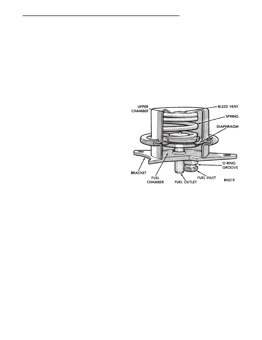
FUEL PRESSURE REGULATOR
The pressure regulator is a mechanical device lo-
cated at the top of the throttle body (Fig. 17). Its
function is to maintain a constant 270 kPa (39 PSI)
across the fuel injector tip.
The regulator uses a spring loaded rubber dia-
phragm to uncover a fuel return port. When the fuel
pump becomes operational, fuel flows past the injec-
tor into the regulator, and is restricted from flowing
any further by the blocked return port. When fuel
pressure reaches 270 kPa (39 PSI) it pushes on the
diaphragm, compresses the spring, and uncovers the
fuel return port. The diaphragm and spring con-
stantly move from an open to closed position keeping
fuel pressure consistent.
THROTTLE BODY
The throttle body assembly (Fig. 18) is mounted on
top of the intake manifold. It contains the fuel injec-
tor, pressure regulator, throttle position sensor and
idle air control motor. Air flow through the throttle
body is controlled by a cable operated throttle blade
located in the base of the throttle body. The throttle
body itself provides the chamber for metering, atom-
izing, and mixing fuel with the air entering the en-
gine.
Fig. 17 Fuel Pressure Regulator
Ä
FUEL SYSTEMS
14 - 33
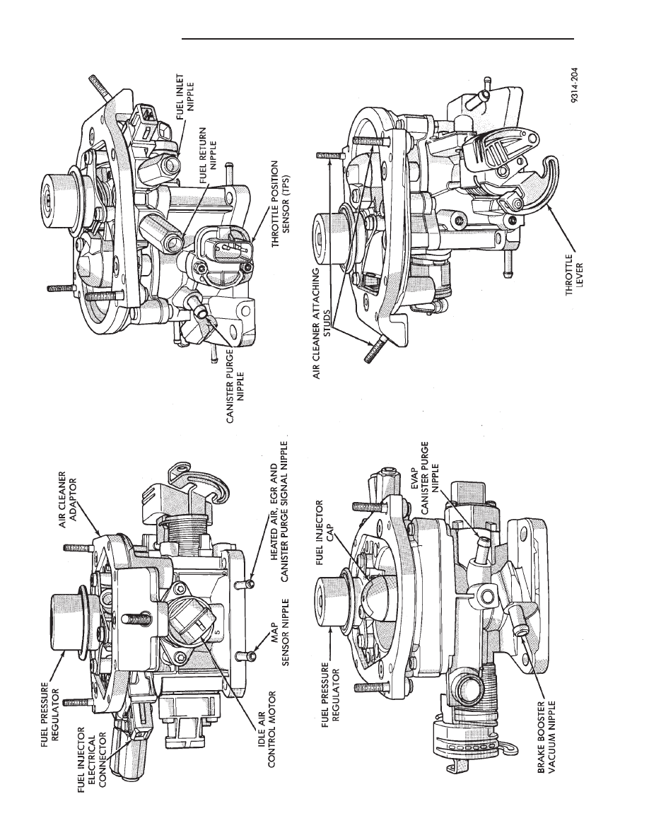
Fig.
18
Throttle
Body
14 - 34
FUEL SYSTEMS
Ä
2.2L/2.5L SINGLE POINT FUEL INJECTION—GENERAL DIAGNOSIS
INDEX
page
page
Fuel System Diagram
. . . . . . . . . . . . . . . . . . . . . 35
Visual Inspection
. . . . . . . . . . . . . . . . . . . . . . . . . 35
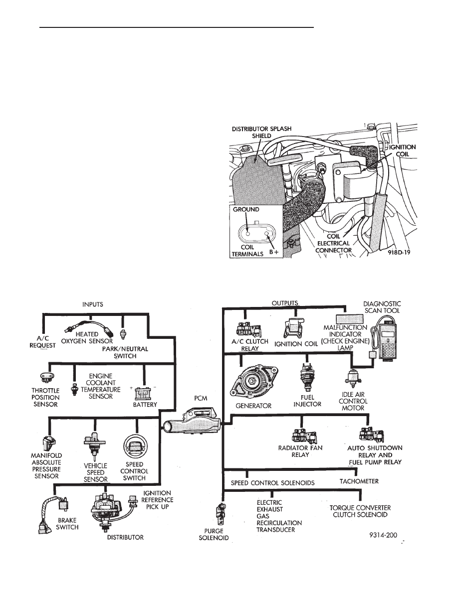
FUEL SYSTEM DIAGRAM
The fuel injection system is managed by the pow-
ertrain control module (PCM). The PCM receives in-
puts from various switches and sensors (Fig. 1).
Based on these inputs the PCM adjusts ignition tim-
ing and idle speed through output devices. Refer to
the Single Point Fuel Injection System Operation
section of this group for system and component de-
scriptions.
VISUAL INSPECTION
Perform a visual inspection for loose, disconnected,
or misrouted wires and hoses before diagnosing or
servicing the fuel injection system. A visual check
helps save unnecessary test and diagnostic time. A
thorough visual inspection includes the following
checks:
(1) Check Ignition Coil Electrical Connections (Fig.
2).
Fig. 1 Single Point Fuel Injection Components
Fig. 2 Ignition Coil
Ä
FUEL SYSTEMS
14 - 35

(2) Verify the electrical connector is attached to
the Canister Purge Solenoid (Fig. 3).
(3) Verify vacuum connection at Canister Purge
Solenoid is secure and not leaking.
(4) Verify the wiring connector is attached to the
Electric EGR Transducer (EET) solenoid (Fig. 4).
(5) Verify vacuum connection at the Electric EGR
Transducer is secure and not leaking (Fig. 4).
(6) Verify the connector is attached to the MAP
sensor (Fig. 5).
(7) Verify the vacuum hose is attached to the MAP
sensor (Fig. 5).
(8) Verify the generator wiring and belt are cor-
rectly installed and tightened.
(9) Verify hoses are securely attached to the EVAP
canister (Fig. 6).
(10) Verify the throttle body wiring connection to
main harness is attached (Fig. 7).
(11) Verify the electrical connector is attached to
idle air control motor (Fig. 8).
(12) Verify the electrical connector is attached to
the throttle position sensor (Fig. 8).
(13) Verify the electrical connector is attached to
the fuel injector (Fig. 8).
(14) Verify the hose from PCV valve is securely at-
tached to the intake manifold vacuum port (Fig. 9).
(15) Verify vacuum connections on the front and
rear of Throttle Body are secure and not leaking
(Figs. 10 and 11).
Fig. 3 Canister Purge Solenoid
Fig. 4 Electric EGR Transducer (EET) Assembly
Fig. 5 Manifold Absolute Pressure (MAP) Sensor
Fig. 6 EVAP Canister
Fig. 7 Throttle Body Wiring Connection to Main
Harness
14 - 36
FUEL SYSTEMS
Ä
Нет комментариевНе стесняйтесь поделиться с нами вашим ценным мнением.
Текст