Chrysler Le Baron, Dodge Dynasty, Plymouth Acclaim. Manual — part 168
HEAD LINING
REMOVAL
(1) Disconnect battery negative cable.
(2) Pull dome lamp downward to disengage from
retaining ring in head lining. Separate lens from
lamp body and remove bulb. Separate bulb holder
from lamp body. Remove attaching screw holding re-
taining ring to roof bow, if equipped.
(3) Remove screws holding coat hooks to roof above
quarter panels.
(4) Remove roof rail and A-pillar mouldings.
(5) Remove screws holding sun visors to roof
header and disconnect wire connector, if equipped.
Remove inboard sun visor hangers.
(6) Remove overhead console, if equipped.
(7) Pull front reading lamp downward to disengage
from retaining ring in head lining and disconnect
wire connector. Remove screws holding retaining
ring to roof header, if equipped.
(8) Remove pinch welt holding headlining to sun
roof opening, if equipped.
(9) Remove one quarter trim panel as necessary to
clear head lining removal path.
(10) Disengage hook and loop fasteners holding
head lining to roof above rear window and slide head
lining from behind quarter panel.
(11) Remove head lining from vehicle.
INSTALLATION
Reverse the preceding operation.
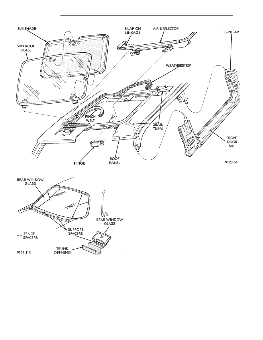
SUN ROOF WEATHERSTRIP
REMOVAL (FIG. 22)
(1) Remove sun roof sunshade and glass. Refer to
Owner’s Manual for instructions.
(2) Pull weatherstrip from pinch flange around sun
roof opening.
INSTALLATION
Reverse the preceding operation.
SUN ROOF AIR DEFLECTOR
REMOVAL (FIG. 22)
(1) Remove sun roof sunshade and glass. Refer to
Owner’s Manual for instructions.
(2) Disengage snap-on linkage at rear of air deflec-
tor in sun roof opening.
(3) Remove screws holding air deflector to front of
sun roof opening.
INSTALLATION
Reverse the preceding operation.
SUN ROOF DRAIN TUBES
REMOVAL (FIG. 22)
(1) Remove head lining as necessary.
(2) Remove A-pillar or quarter trim covers as nec-
essary.
(3) Remove cowl panel and sill plate trim as neces-
sary.
(4) Disconnect effected drain tube from nipple at
sun roof opening.
(5) Pull drain tube upward to remove from pillar
involved.
INSTALLATION
Reverse the preceding operation. Route the tube to
avoid kinks or puncture from sharp edges.
REAR WINDOW GLASS
REMOVAL (FIG. 23)
(1) Remove rear window mouldings.
(2) Remove interior trim as necessary to gain ac-
cess to rear window defogger wire connector and
ground screw, if equipped.
WARNING: WEAR EYE AND HAND PROTECTION
WHEN HANDLING SAFETY GLASS. PERSONAL IN-
JURY CAN RESULT.
CAUTION: Do not damage body or trim finish when
cutting out glass or applying fence primer.
(3) Cut the urethane around the perimeter of the
back window glass. Refer to Windshield section of
this group for proper procedures.
(4) Separate the rear window from the vehicle.
INSTALLATION
(1) Prepare the work area, window fence, and glass
the same way as described in the Windshield section
of this group.
(2) Place fence spacers at the locations shown (Fig.
23).
(3) Apply a 10 mm (0.4 in.) bead of urethane
around the perimeter of the glass.
(4) Install the glass in the same manner described
in the Windshield section of this group.
(5) Install the rear window moulding.
(6) Connect rear window defogger wiring and in-
stall interior trim.
(7) After urethane has cured, water test rear win-
dow to verify repair. Verify rear window defogger op-
eration, see Group 8N, Rear Window Defogger.
Ä
AJ-BODY
23 - 81
TRUNK LID
REMOVAL (FIG. 24)
(1) Raise trunk lid to full up position.
(2) Disconnect the trunk lamp wire connector.
(3) Mark all bolt and hinge attachment locations
with a grease pencil or other suitable device to pro-
vide reference marks for installation. When install-
ing trunk lid, align all marks and secure bolts. The
trunk lid should be aligned to 4 mm (0.160 in.) gap
to the quarter panels and flush across the top sur-
faces along quarter panels.
(4) Remove the top trunk lid to hinge attaching
bolts and loosen the bottom bolts until they can be
removed by hand.
(5) With assistance of a helper at the opposite side
of the vehicle to support the trunk lid, remove the
bottom trunk lid to hinge attaching bolts. Separate
the trunk lid from the vehicle.
INSTALLATION
Reverse the preceding operation.
TRUNK LID HINGE
REMOVAL
(1) Remove rear parcel shelf trim cover.
(2) Disconnect trunk lid lift torsion bars from
hinges.
(3) Mark all attaching bolt, nut, and component lo-
cations with a suitable marking device. Use marks
as a reference when installing hinge.
(4) Remove bolts holding trunk lid to hinge.
(5) Remove nuts and bolts holding hinge to closure
panel below rear window glass.
(6) Separate hinge from vehicle.
INSTALLATION
Reverse the preceding operation.
Fig. 22 Sun Roof
Fig. 23 Rear Window Glass
23 - 82
AJ-BODY
Ä

TRUNK LID TORSION BAR
REMOVAL
(1) Raise and support trunk lid in the full up posi-
tion.
(2) Remove trunk lining as necessary to gain ac-
cess to torsion bars.
(3) Disengage adjusting end of torsion bar from the
slot in the tension adjustment bracket.
(4) Pivot torsion bar out of lift arm swivel.
(5) Disconnect torsion bar from hinge.
INSTALLATION
Reverse the preceding operation.
TRUNK LID LATCH
REMOVAL
(1) Raise trunk lid to the full up position.
(2) Remove push-in fasteners holding lining to
trunk lid as necessary.
(3) Disconnect remote release cable from latch.
(4) Remove bolts holding latch to trunk lid and
separate latch from vehicle.
INSTALLATION
Insert trunk lock chill into latch release driver and
reverse the preceding operation.
TRUNK LID LOCK
REMOVAL
(1) Remove trunk lid tail light assembly. Refer to
Group 8L, Lamps for proper procedures.
(2) Remove trunk latch.
(3) Remove nuts holding lock cylinder and chill to
trunk lid and separate the lock from the vehicle.
INSTALLATION
Reverse the preceding operation.
TRUNK OPENING WEATHERSTRIP
REMOVAL (FIG. 25)
(1) Raise trunk lid to the full up position.
(2) Pull the weatherstrip from the pinch flange
around the trunk opening.
INSTALLATION
A new trunk lid opening weatherstrip should be
heated to approximately 38° C (100° F) before instal-
lation. The weatherstrip butt splice should be located
at the center rear of trunk opening. Reverse the re-
moval operation. After weatherstrip has been in-
stalled, close trunk lid and allow weatherstrip to
cool. The weatherstrip will form to the trunk lid con-
tour as it cools.
TRUNK LID LUGGAGE RACK
REMOVAL (FIG. 26)
(1) Remove screws holding spoiler to trunk lid.
(2) Pry rub strip inserts from skid strips.
(3) Remove screws holding skid strips to trunk lid.
INSTALLATION
Reverse the preceding operation
TRUNK LID AND FUEL FILL DOOR RELEASE
CABLES
REMOVAL (FIG. 27)
(1) Remove interior trim as necessary to gain ac-
cess to release cables.
(2) Remove left front door scuff plate.
(3) Remove screw holding trim cover to release ca-
ble handle and separate cover from handle.
(4) Remove screw holding release handle to door
sill.
(5) Pry open retainer tab holding cable core end in
handle pivot. Pry cable case end from handle.
(6) Remove trunk lining as necessary to gain ac-
cess to the release cables.
Fig. 24 Trunk Lid—Typical
Fig. 25 Trunk Opening Weatherstrip—Typical
Ä
AJ-BODY
23 - 83

(7) On fuel fill door cable, remove nut holding ca-
ble latch to fuel fill opening.
(8) On trunk lid latch, remove trunk latch cover
and disconnect cable end from latch. Route cable
back through trunk lid.
INSTALLATION
Reverse the preceding operation.
FUEL FILL DOOR
REMOVAL (FIG. 28)
(1) Open fuel fill door.
(2) Separate trunk lining from right quarter panel.
(3) Remove nuts holding fuel fill door to quarter
panel.
(4) Separate fuel fill door from quarter panel open-
ing.
INSTALLATION
Reverse the preceding operation. Align to achieve
equal spacing around fuel fill door and flush to the
quarter panel.
Fig. 26 Trunk Lid Luggage Rack
Fig. 27 Trunk Lid and Fuel Fill Door Release Cables
Fig. 28 Fuel Fill Door—Typical
23 - 84
AJ-BODY
Ä
Нет комментариевНе стесняйтесь поделиться с нами вашим ценным мнением.
Текст