Chrysler Le Baron, Dodge Dynasty, Plymouth Acclaim. Manual — part 166
(4) Remove hood latch release cable handle attach-
ing bolts from under left lower edge of instrument
panel.
(5) Disengage release cable rubber grommet from
engine compartment dash panel behind instrument
panel.
(6) Rout cable assembly through engine compart-
ment around battery, under fender lip, under relay
bank, and under wiring harnesses, toward dash
panel. Push cable through access hole in dash panel
under the brake master cylinder, into passenger com-
partment.
HOOD LATCH RELEASE CABLE
INSTALLATION
Reverse the preceding operation.
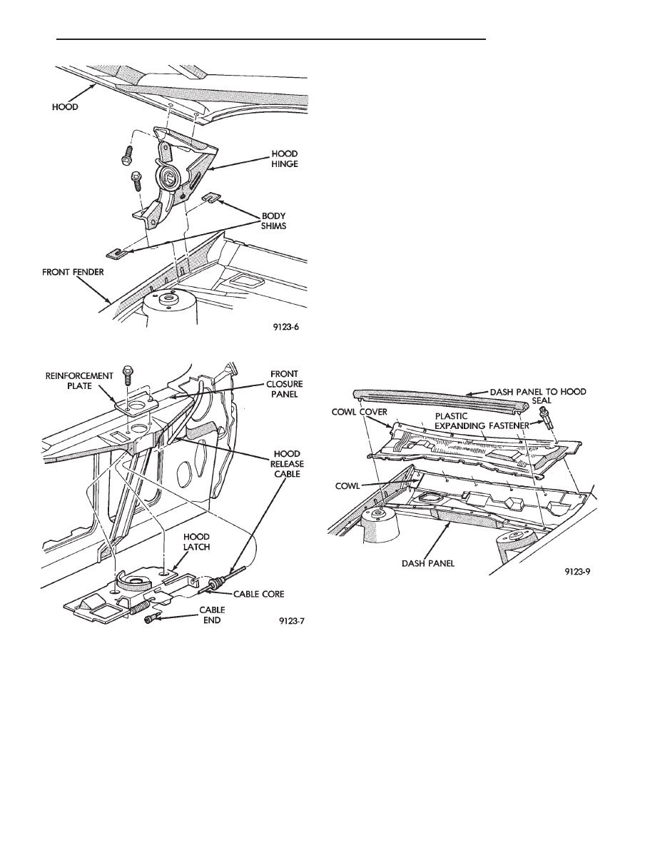
COWL COVER
REMOVAL (FIG. 5)
(1) Raise hood to full up position.
(2) Disconnect windshield washer hoses from wiper
arms.
(3) Remove windshield wiper arm assemblies. Re-
fer to Group 8K, Windshield Wiper and Washer Sys-
tems.
(4) Remove plastic expanding type fasteners hold-
ing cowl cover to cowl, below windshield.
(5) Lift back of cowl cover and slide cover rearward
from under dash panel to hood seal and separate
cover from vehicle.
INSTALLATION
Reverse the preceding operation.
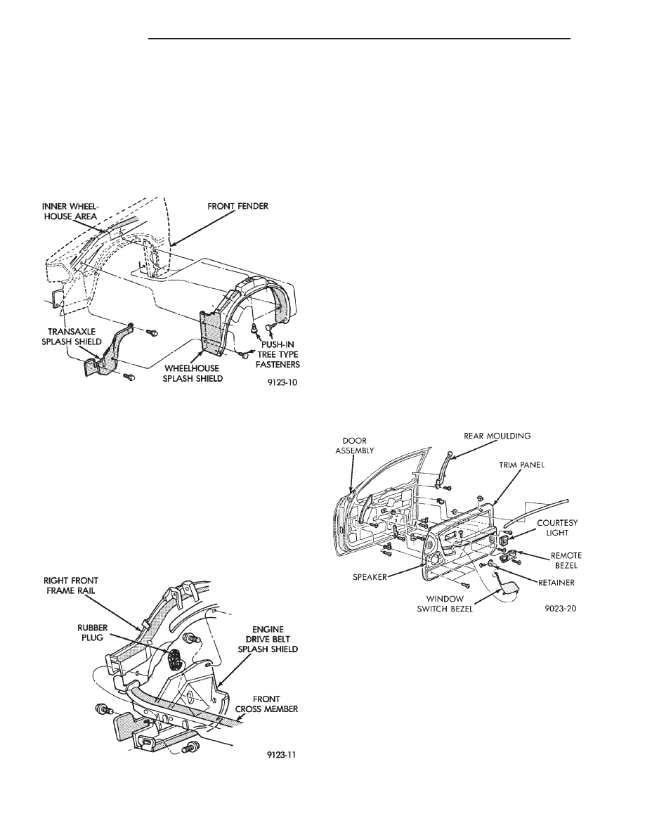
FRONT END SPLASH SHIELDS
FRONT WHEELHOUSE SPLASH SHIELD
REMOVAL (FIG. 6)
(1) Hoist vehicle and support on suitable safety
stands.
(2) Remove front wheel assembly.
(3) Remove push-in fasteners holding front wheel-
house splash shield to fender opening lip and inner
wheelhouse area.
(4) Separate wheelhouse splash shield from vehi-
cle.
FRONT WHEELHOUSE SPLASH SHIELD
INSTALLATION
Reverse the preceding operation.
Fig. 3 Hood Hinge Assembly—Typical
Fig. 4 Hood Latch Assembly—Typical
Fig. 5 Cowl Cover Assembly
Ä
AJ-BODY
23 - 73
TRANSAXLE SPLASH SHIELD REMOVAL (FIG.
6)
(1) Remove one front wheelhouse splash shield
push-in fastener and separate wheelhouse splash
shield from transaxle splash shield.
(2) Remove transaxle splash shield attaching bolts
and separate transaxle splash shield from vehicle.
TRANSAXLE SPLASH SHIELD INSTALLATION
Reverse the preceding operation.
ENGINE DRIVE BELT SPLASH SHIELD
REMOVAL (FIG. 7)
(1) Hoist vehicle and support on suitable safety
stands.
(2) Remove bolts holding engine drive belt splash
shield to right frame rail.
(3) Separate drive belt splash shield from vehicle.
ENGINE DRIVE BELT SPLASH SHIELD
INSTALLATION
Reverse the preceding operation.
DOOR TRIM PANEL
REMOVAL (FIG. 8)
(1) Lower door glass and disconnect battery nega-
tive cable.
(2) Remove courtesy lamp and remove socket.
(3) Remove screw holding trim panel to door from
courtesy lamp opening.
(4) Disengage clips holding speaker grille to trim
panel and separate grille from door.
(5) Remove screw holding trim panel to door from
speaker grille opening.
(6) Remove screw holding inside latch handle bezel
to trim panel and separate bezel from door. Discon-
nect power door lock switch wire connector, if
equipped.
(7) Remove window crank, if equipped.
(8) Remove screw holding trim panel to door from
arm rest pull cup opening.
(9) Remove hidden screws holding trim panel to
door from carpet area at bottom of trim.
(10) Lift trim panel upward and separate panel
from door.
(11) Disconnect radio speaker, power window and
power mirror wire connectors, if equipped.
INSTALLATION
Reverse the preceding operation.
FRONT DOOR SILENCER AND WATER SHIELD
REMOVAL (FIG. 9)
(1) Remove front door trim panel.
(2) Remove push-in fasteners holding silencer pad
to door inner panel and separate silencer from door.
(3) Pull water shield from adhesive around perim-
eter of door inner panel.
INSTALLATION
Reverse the preceding operation.
Fig. 6 Front Wheelhouse and Transaxle Splash
Shields—Typical
Fig. 7 Engine Drive Belt Splash Shield—Typical
Fig. 8 Door Trim Panel
23 - 74
AJ-BODY
Ä
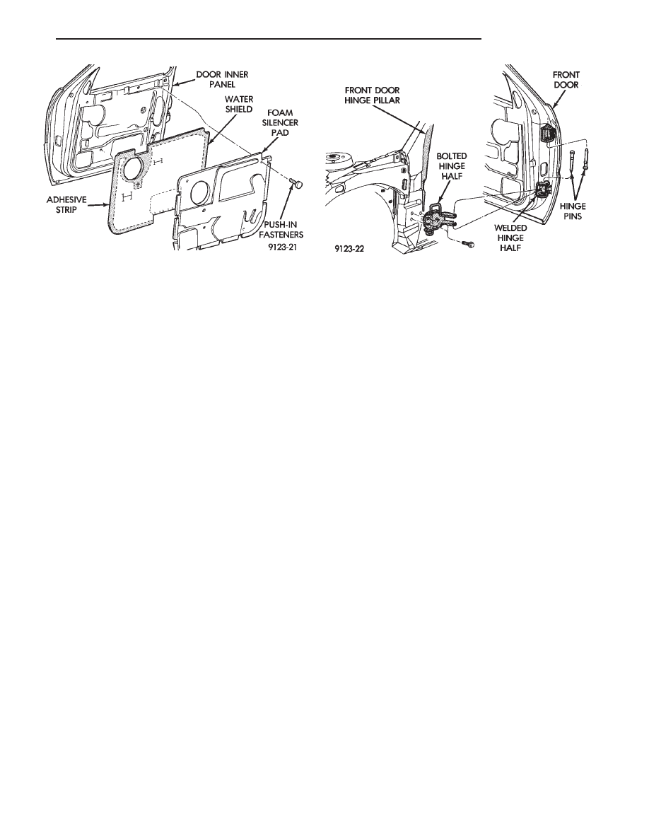
FRONT DOOR AND HINGE
The front door hinge is welded to the door and
bolted to the hinge pillar. The door half of the hinge
pivots on a removable hinge pin. The hinge pin is
driven in from the bottom on the top hinge and from
the top on the bottom hinge. All adjustments to the
hinge are performed on the hinge pillar half of the
hinge. If the welded half of the hinge must be bent to
align door, consult an authorized body repair facility.
FRONT DOOR REMOVAL (FIG. 10)
(1) Remove door trim panel, silencer pad, and wa-
ter shield.
(2) Disconnect all wire connectors and wire har-
ness hold downs inside door and push wire harness
through access hole in front of door into hinge pillar
opening.
(3) Open door and support door on a suitable lift-
ing device.
(4) Drive bottom hinge pin upward and remove pin
from hinge.
(5) Drive top hinge pin downward and remove pin
from hinge.
FRONT DOOR INSTALLATION
Reverse the preceding operation. The door should
not require re-alignment. If door does need align-
ment, refer to Front Door Hinge Installation para-
graph in this section.
FRONT DOOR HINGE REMOVAL (FIG. 10)
(1) Remove front fender wheelhouse splash shield.
Refer to Front Wheelhouse Splash Shield Removal
paragraph in this section.
(2) Support door on a suitable lifting device.
(3) Drive out hinge pin on the effected hinge.
(4) Remove bolts holding hinge to hinge pillar and
separate hinge form vehicle.
FRONT DOOR HINGE INSTALLATION
Reverse the preceding operation. Align door to
achieve 6 mm (0.240 in.) gap to all surrounding pan-
els and flush across gaps.
DOOR LATCH
REMOVAL
(1) Remove door trim panel.
(2) Remove silencer and water shield, as necessary.
(3) Raise door glass to up position.
(4) Disconnect linkage rods from door latch assem-
bly.
(5) Remove screws holding latch top door end
frame.
(6) Separate latch from door.
INSTALLATION
Reverse the preceding operation.
WINDOW REGULATOR
REMOVAL
(1) Remove door trim panel.
(2) Remove silencer and water shield as necessary.
(3) Raise glass to 25 mm (1 in.) below full up posi-
tion and support glass lift plate to keep the glass
from falling.
(4) Disconnect power window motor wire connec-
tor, if equipped.
(5) Remove rivets holding regulator to inner door
panel using a 6 mm (0.250 in) drill.
(6) Slide regulator lift arm roller from lift plate
channel.
(7) Remove regulator assembly through access hole
in door.
INSTALLATION
Reverse the preceding operation.
Fig. 9 Front Door Silencer and Water
Shield—Typical
Fig. 10 Front Door Assembly
Ä
AJ-BODY
23 - 75
DOOR GLASS
REMOVAL
(1) Remove door trim panel.
(2) Remove silencer and water shield.
(3) Raise door glass 100 mm (4 in.) from down po-
sition.
(4) Disconnect battery negative cable if equipped
with power windows.
(5) Loosen bolts holding glass stabilizers and guide
hook receiver to top of inner door frame.
(6) Remove nuts holding door glass to lift plate.
(7) Separate glass from lift plate and lift glass up-
ward from opening at top of door.
INSTALLATION
Reverse the preceding operation.
DOOR GLASS LIFT PLATE AND GUIDE POST
REMOVAL
(1) Remove door trim panel.
(2) Remove silencer and water shield.
(3) Raise door glass 100 mm (4 in.) from down po-
sition.
(4) Disconnect battery negative cable if equipped
with power windows.
(5) Remove nuts holding door glass to lift plate
and separate glass from lift plate. Allow glass to
slide downward to the bottom of door.
(6) Remove bolts (nuts on AJ-27 body) holding
guide post to inner door panel.
(7) Separate lift plate channel from regulator lift
roller.
(8) Remove lift plate and guide assemble from door
through access hole in inner door panel.
INSTALLATION
Reverse the preceding operation.
GLASS RUN WEATHERSTRIP—AJ-21 BODY
REMOVAL
(1) Remove door trim panel.
(2) Remove silencer and water shield as necessary.
(3) Remove side view mirror cover.
(4) Pull glass run weatherstrip from door frame
channel.
INSTALLATION
Reverse the preceding operation.
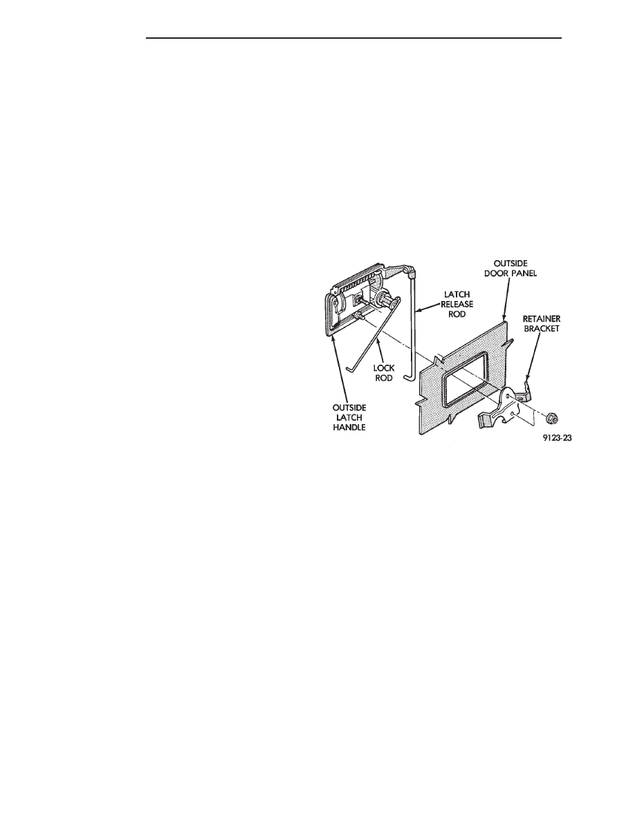
OUTSIDE DOOR LATCH RELEASE HANDLE
REMOVAL (FIG. 11)
(1) Remove door trim panel, silencer pad, and wa-
ter shield.
(2) Raise door glass to full up position.
(3) Disconnect security alarm switch and illumi-
nated entry switch from back of outside front door
latch release handle, if equipped. For additional in-
formation refer to Group 8Q, Vehicle Theft Security
System
(4) Disconnect lock rod and latch release rod from
door latch assembly.
(5) Remove nuts holding outside door latch handle
to retainer bracket and separate bracket from door.
(6) Swing lock rod upward, parallel to back of
latch handle, and separate latch handle from door
panel.
INSTALLATION
Reverse the preceding operation.
INSIDE LATCH RELEASE HANDLE
REMOVAL
(1) Remove door trim panel.
(2) Remove screw holding handle to inner door
panel.
(3) Disconnect linkage rod from back of handle.
(4) Separate handle from door.
INSTALLATION
Reverse the preceding operation.
POWER DOOR LOCK ACTUATOR
REMOVAL
(1) Remove door trim panel. Remove silencer and
water shield as necessary.
(2) Raise door glass to the up position.
(3) Disconnect battery negative cable.
(4) Disconnect lock actuator linkage rod from door
latch.
(5) Remove bolts holding actuator to inner door
panel.
(6) Separate power door lock actuator from door.
Fig. 11 Outside Door Latch Release Handle—Typical
23 - 76
AJ-BODY
Ä
Нет комментариевНе стесняйтесь поделиться с нами вашим ценным мнением.
Текст