Chrysler Le Baron, Dodge Dynasty, Plymouth Acclaim. Manual — part 167
INSTALLATION
Reverse the preceding operation.
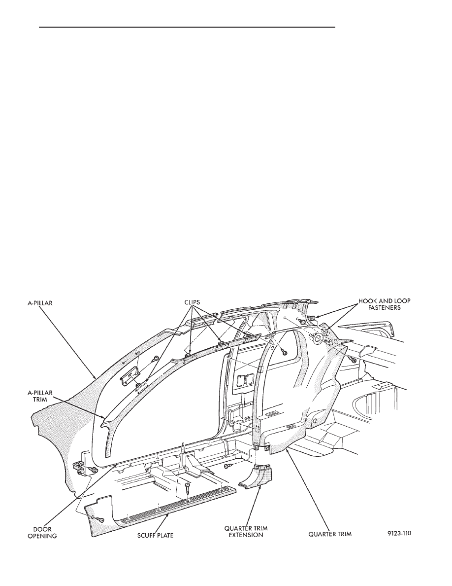
COWL PANEL TRIM AND SCUFF PLATES
COWL PANEL AND DOOR OPENING SCUFF
PLATE REMOVAL (FIG. 12)
(1) Open front door.
(2) Remove screw holding trim panel to cowl for-
ward of the front door opening.
(3) Remove screws holding scuff plate to door sill.
(4) Separate cowl panel trim and scuff plate from
vehicle.
COWL PANEL AND DOOR OPENING SCUFF
PLATE INSTALLATION
Reverse the preceding operation.
A-PILLAR AND ROOF RAIL MOULDINGS
A-PILLAR MOULDING REMOVAL (FIG. 12)
(1) Open front door.
(2) Disengage clips holding A-pillar moulding to
roof rail above door opening.
(3) Slide A-pillar moulding upward and pull rear-
ward to separate moulding from A-pillar.
A-PILLAR MOULDING INSTALLATION
Reverse the preceding operation.
QUARTER TRIM PANEL
QUARTER TRIM PANEL REMOVAL (FIG. 12)
(1) Remove A-pillar moulding and scuff plate as
necessary.
(2) Remove front shoulder harness turning loop
cover. Remove bolt holding turning loop to quarter
panel.
(3) Remove bolt holding rear shoulder harness an-
chor to floor.
(4) Remove rear seat cushion and back.
(5) Remove screw holding quarter trim to roof rail.
(6) Remove quarter trim extension panel. Remove
screws holding quarter trim panel to wheelhouse
kickup.
(7) Remove rear reading lamp. Remove screw hold-
ing quarter trim to roof from lamp opening.
(8) Pull trim panel forward and separate from ve-
hicle.
QUARTER TRIM PANEL INSTALLATION
Reverse the preceding operation.
QUARTER EXTENSION TRIM PANEL
REMOVAL (FIG. 13)
(1) Remove quarter trim panel.
Fig. 12 Interior Mouldings, Panels, and Trim Covers
Ä
AJ-BODY
23 - 77
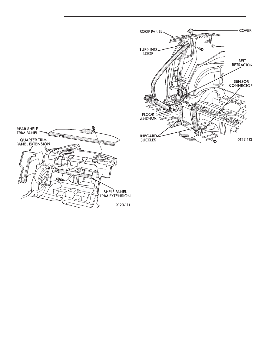
(2) Disengage clips holding expansion trim panel
to shelf panel.
(3) Separate trim panel from vehicle.
INSTALLATION
Reverse the preceding operation.
REAR SHELF TRIM PANEL
REMOVAL (FIG. 13)
(1) Remove one quarter trim panel.
(2) Remove center high mounted stop lamp cover.
Refer to Group 8L, Lamps for instructions.
(3) Disengage screws holding trim to shelf panel
and separate trim from vehicle.
INSTALLATION
Reverse the preceding operation.
FRONT SEAT BELTS
OUTBOARD SHOULDER HARNESS/LAP BELT
REMOVAL (FIG. 14)
(1) Remove quarter trim panel.
(2) Remove bolt holding seat belt retractor to quar-
ter panel.
(3) Separate retractor from vehicle.
OUTBOARD SHOULDER HARNESS/LAP BELT
INSTALLATION
Reverse the preceding operation.
INBOARD SEAT BELT BUCKLE REMOVAL
(FIG. 14)
(1) Remove bolt holding inboard buckle to floor.
(2) Disconnect seat belt sensor wire connector.
(3) Separate buckle assembly from vehicle.
INBOARD SEAT BELT BUCKLE
INSTALLATION
Reverse the preceding operation.
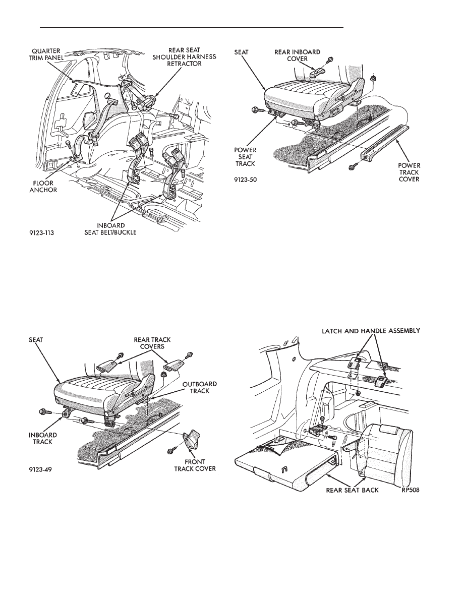
REAR SEAT BELTS
OUTBOARD SHOULDER HARNESS/LAP BELT
REMOVAL (FIG. 15)
(1) Remove quarter trim panel.
(2) Remove bolt holding lap belt to floor at wheel-
house kickup.
(3) Remove bolt holding seat belt retractor to quar-
ter panel.
OUTBOARD SHOULDER HARNESS/LAP BELT
INSTALLATION
Reverse the preceding operation.
INBOARD BUCKLE/CENTER OCCUPANT
BELTS REMOVAL (FIG. 15)
(1) Remove rear seat cushion.
(2) Remove bolt holding inboard buckle/center oc-
cupant belt to floor.
(3) Separate buckle/belt assembly from vehicle.
INBOARD BUCKLE/CENTER OCCUPANT BELT
INSTALLATION
Reverse the preceding operation.
FRONT SEATS
FRONT SEAT REMOVAL (FIG. 16 OR 17)
(1) Position seat full forward.
(2) Remove screws holding rear track riser covers
and separate covers from tracks.
(3) On power seat track, remove outboard track
cover.
(4) Remove nuts holding seat track to floor.
(5) Position seat full rearward.
Fig. 13 Quarter Trim Extension and Shelf Trim
Panels
Fig. 14 Front Seat Belts
23 - 78
AJ-BODY
Ä
(6) On power seat track, remove door sill scuff
plate and disconnect wire connector.
(7) Remove bolts holding seat track to cross mem-
ber.
(8) Remove seat from vehicle.
FRONT SEAT INSTALLATION
Reverse the preceding operation.
REAR SEATS
REAR SEAT CUSHION REMOVAL
(1) Remove bolts holding cushion to floor.
(2) Push center occupant seat belts through open-
ings in cushion.
(3) Remove cushion from vehicle.
REAR SEAT CUSHION INSTALLATION
Reverse the preceding operation.
REAR SEAT BACK REMOVAL (FIG. 18)
(1) Hinge seat back forward and disengage push-in
fasteners holding carpet backing to trunk floor.
(2) Remove bolts holding outboard hinge pivot
bracket to seat back.
(3) Pull seat back outward to disengage inboard
pivot and separate from vehicle.
REAR SEAT BACK INSTALLATION
Reverse the preceding operation.
FRONT CENTER CONSOLE
REMOVAL (FIG. 19)
(1) Position front seats full forward.
(2) Remove rear ash tray.
(3) Remove rear lower carpeted end cover.
Fig. 15 Rear Seat Belts
Fig. 16 Manual Front Seat
Fig. 17 Power Front Seat
Fig. 18 Rear Seat Cushion and Back
Ä
AJ-BODY
23 - 79

(4) Remove nuts holding console to floor bracket.
(5) Position front seats full rearward.
(6) Raise console storage bin cover and remove bot-
tom mat.
(7) Remove screws holding bottom of storage bin to
floor bracket.
(8) Remove screws holding console side panels to
instrument panel. Disengage hook and loop fasteners
and separate side panels from console.
(9) Disconnect shift indicator cable and clip from
shift mechanism through right side panel opening, if
equipped with automatic transaxle. Refer to Group
8E, Instrument Panel and Gauges for proper service
procedures.
(10) Disengage clips holding parking brake lever
cover to console and separate cover from vehicle.
(11) Remove center instrument panel bezel. Refer
to Group 8E, Instrument Panel. Remove screws hold-
ing console to instrument panel.
(12) Remove screws holding console to lower in-
strument panel.
(13) Remove bolts holding console to forward floor
mounting bracket.
(14) Remove gear selector knob.
(15) Separate console from floor and remove from
vehicle.
INSTALLATION
Reverse the preceding operation.
FLOOR CARPET
REMOVAL (FIG. 20)
(1) Remove cowl trim panels and scuff plates.
(2) Remove front seats and inboard seat belts.
(3) Remove center arm rest and front console.
(4) Remove outboard seat belt lower attaching
bolts.
(5) Remove left dash panel foot rest.
(6) Remove rear seat cushion.
(7) Pull carpet from under quarter trim covers.
(8) Fold carpet and remove through door opening.
INSTALLATION
Reverse the preceding operation.
OVERHEAD CONSOLE
REMOVAL (FIG. 21)
(1) Remove screws holding overhead console to re-
inforcement bracket.
(2) Slide overhead console rearward to separate re-
inforcement bracket retainer tab from console.
(3) Lower console from roof and disconnect wire
connectors.
INSTALLATION
Reverse The preceding operation.
Fig. 19 Center Console
Fig. 20 Floor Carpet and Silencers—Typical
Fig. 21 Overhead Console—Typical
23 - 80
AJ-BODY
Ä
Нет комментариевНе стесняйтесь поделиться с нами вашим ценным мнением.
Текст