Chrysler Le Baron, Dodge Dynasty, Plymouth Acclaim. Manual — part 30
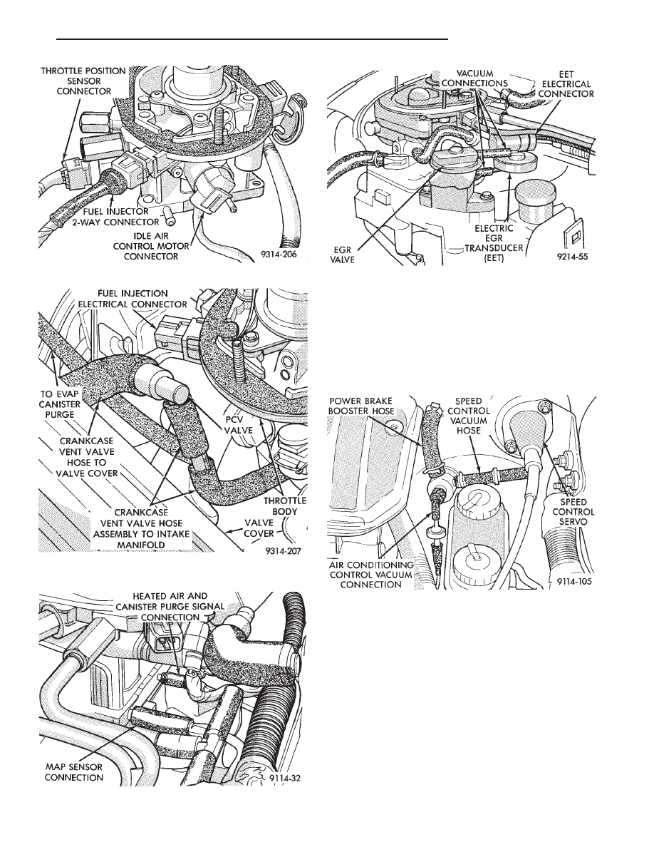
(16) Verify hoses are attached to back pressure
transducer or electric EGR transducer (EET) (Fig.
11).
(17) Verify heated air door vacuum connection is
connected and not leaking.
(18) Verify power brake and speed control vacuum
connectors are tight (Fig. 12).
(19) Verify all ignition cables are in correct order
and seated into place (Fig. 13).
(20) Verify the electrical connector is attached to
coolant temperature sensor (Fig. 14).
(21) Verify
battery
negative
ground
eyelet
is
mounted to the cylinder head (Figs. 14).
(22) Verify electrical connector is attached to dis-
tributor (Fig. 15).
(23) Verify radiator fan electrical connector is at-
tached to the harness (Fig. 15).
(24) Verify oil pressure switch electrical connector
is attached to the switch (Fig. 15).
Fig. 9 Vacuum Hose from Intake Manifold to PCV
Valve
Fig. 10 Throttle Body Vacuum Ports—Front
Fig. 8 Throttle Body Wiring Connections
Fig. 11 Throttle Body Vacuum Ports—Rear
Fig. 12 Power Brake and Speed Control Vacuum
Connection
Ä
FUEL SYSTEMS
14 - 37
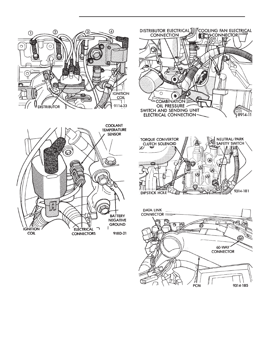
(25) On automatic transaxle equipped vehicles,
verify the park/neutral position switch electrical con-
nector is attached to the switch (Fig. 16).
(26) On automatic transaxle equipped vehicles,
check the torque convertor lockup solenoid electrical
connection (Fig. 16).
(27) Verify the 60-way connector is fully inserted
into the socket on the PCM (Fig. 17).
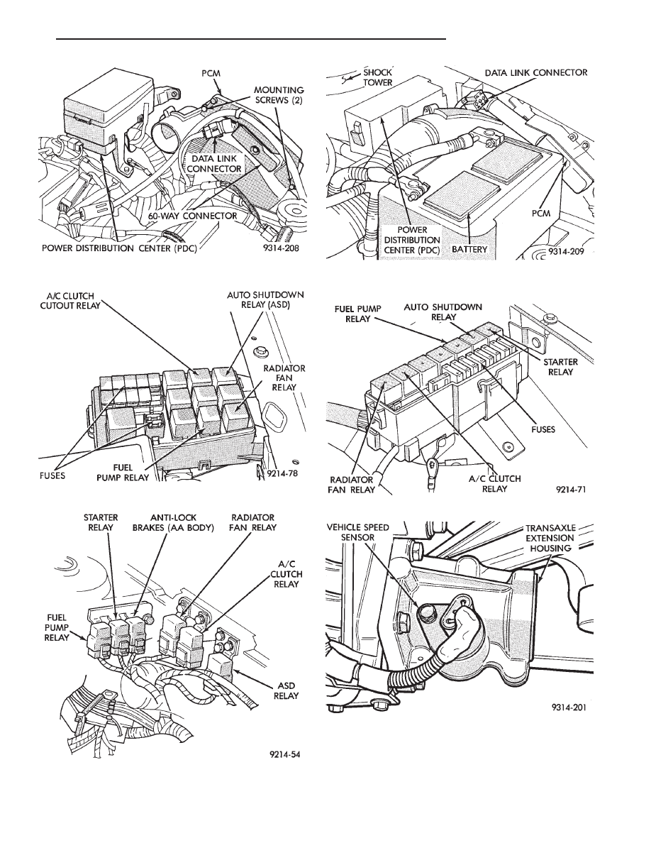
(28) Verify all electrical connectors are fully in-
serted into relays and that battery connections are
clean and tight (Figs. 18, 19, 20, 21, and 22).
Fig. 13 Ignition Cable Routing and Connection
Fig. 14 Coolant Temperature Sensor
Fig. 15 Distributor, Oil Pressure Switch, and
Radiator Fan Electrical Connections
Fig. 16 Automatic Transaxle Electrical Connections
Fig. 17 PCM Electrical Connector
14 - 38
FUEL SYSTEMS
Ä
(29) Verify engine harness to main harness con-
nections are fully inserted.
(30) Check the vehicle speed sensor connector (Fig.
23).
Fig. 18 Power Distribution Center (PDC) (AC Body)
Fig. 19 Relay Identification (AC Body)
Fig. 20 Relay Identification (AA and AP Bodies)
Fig. 21 Power Distribution Center (PDC) (AG and AJ
Body)
Fig. 22 Relay Identification (AG and AJ Body)
Fig. 23 Vehicle Speed Sensor Wiring Connection
Ä
FUEL SYSTEMS
14 - 39
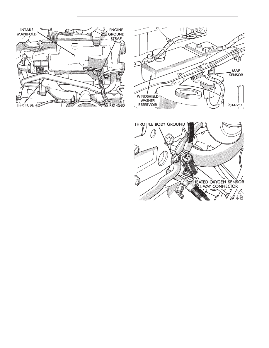
(31) Verify engine ground strap is attached at the
engine and dash panel (Figs. 24 and 25).
(32) Verify oxygen sensor electrical connector is at-
tached to the sensor (Fig. 26).
(33) Check Hose and Wiring Connections at Fuel
Pump. Check that wiring connector is making con-
tact with terminals on pump.
Fig. 24 Engine Ground Strap at Intake Manifold
Fig. 25 Engine Ground Strap to Dash Panel
Fig. 26 Heated Oxygen Sensor Electrical
Connection
14 - 40
FUEL SYSTEMS
Ä
Нет комментариевНе стесняйтесь поделиться с нами вашим ценным мнением.
Текст