SsangYong Korando II (1996-2006 year). Manual — part 15
1B1 -- 26 M162 ENGINE MECHANICAL
DAEWOO MY_2000
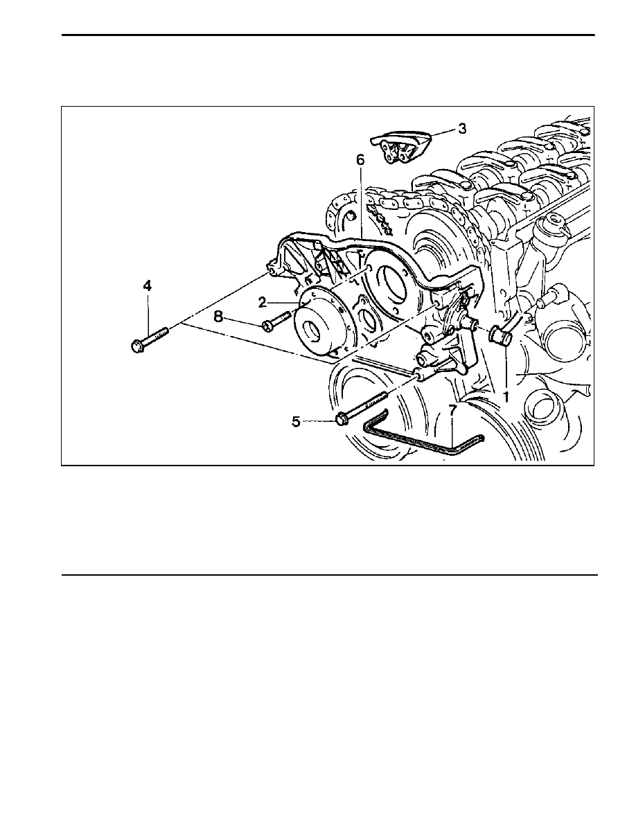
CYLINDER HEAD FRONT COVER
Preceding Work: Removal of cylinder head cover
Removal of coolant connection fitting
1 Camshaft Position Sensor
2 Magnet Assembly
3 Upper Guide Rail
4 Bolt (M6 x 60, 3 pieces)
22.5--27.5 NSm (16.6--20.3 lb-ft)
. . . . . . . . . . . . .
5 Bolt (M8 x 80, 3 pieces)
22.5--27.5 NSm (16.6--20.3 lb-ft)
. . . . . . . . . . . . .
6 Front Cover
7 Rubber Gasket
Replace
. . . . . . . . . . . . . . . . . . . .
8 Bolt (M6 x 16, 3 pieces)
9--11 NSm (80--97 lb-in)
. . . . . . . . . . . . . . . . . . . . .
M162 ENGINE MECHANICAL 1B1 -- 27
DAEWOO MY_2000
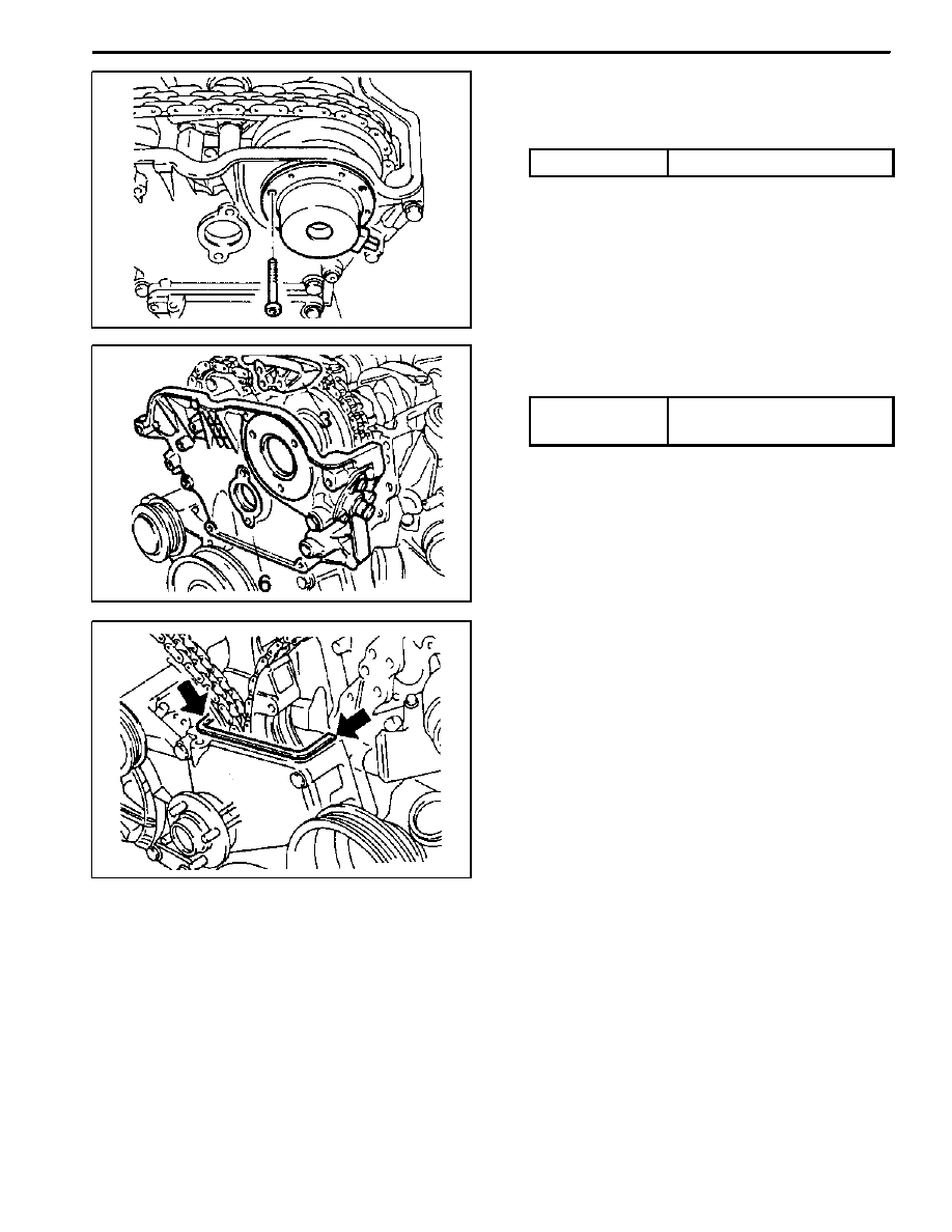
Removal & Installation Procedure
1. Remove the magnet assembly.
Installation Notice
Tightening Torque
9 -- 11 NSm (80 -- 97 lb-in)
2. Remove the cylinder head front cover (6).
Installation Notice
Tightening Torque
22.5 -- 27.5 NSm
(16.6 -- 20.3 lb-ft)
Apply the sealant at the mating surface of the cylinder
head and the front cover.
3. Remove the upper guide rail pin and the guide rail (3).
Installation Notice
Install it while the chain tensioner is loose.
4. Remove the gasket (arrow).
Installation Notice
Replace the gasket with new one and apply the sea-
lant.
5. Installation should follow the removal procedure in
the reverse order.
1B1 -- 28 M162 ENGINE MECHANICAL
DAEWOO MY_2000
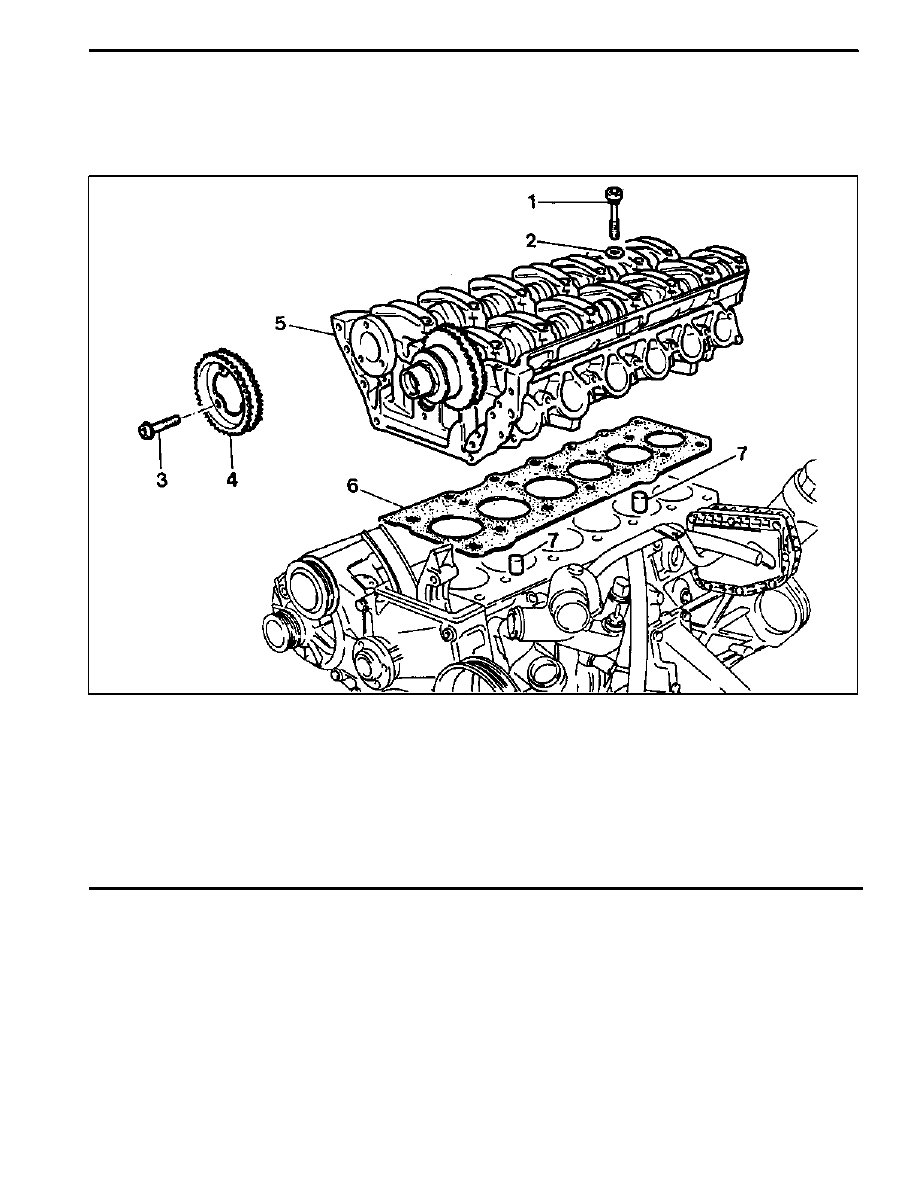
CYLINDER HEAD
Preceding Work: Removal of cylinder head cover
Removal of cylinder head front cover
Removal of upper intake manifold
1 Cylinder Head Bolt (14 pieces)
1st step 55 NSm (41 lb-ft)
. . . . . . . . . . . . . . . . . . .
2nd step 90°
3rd step 90°
2 Washers (14 pieces)
3 Flange Bolts (3 pieces)
1st step 18--22 NSm (13--16 lb-ft)
. . . . . . . . . . . .
2nd step 60° ± 5°
4 Exhaust Camshaft Sprocket
5 Cylinder Head
6 Gasket
Replace
. . . . . . . . . . . . . . . . . . . . . . . . . . .
7 Dowel Sleeve

M162 ENGINE MECHANICAL 1B1 -- 29
DAEWOO MY_2000
Tools Required
617 589 00 10 00 Allen Wrench Socket
116 589 01 34 00 Threaded Pin
116 589 20 33 00 Sliding Hammer
Removal & Installation Procedure
1. Rotate the crankshaft so that the piston of number 1
cylinder is at TDC.
Notice: Rotate the crankshaft in the normal engine di-
rection.
2. Put the alignment marks (arrows) on the timing chain
and camshaft sprocket.
3. Drain the coolant from the crankcase.
4. Remove the three flange bolts in the exhaust cam-
shaft sprocket.
Installation Notice
Tightening Torque
1st step: 18 -- 22 NSm
(13 -- 16 lb-ft)
Tightening Torque
2nd step: 60° ± 5°
Do not reuse the removed bolts.
5. Separate the chain from the camshaft sprocket.
Notice: Be careful not to drop the chain into the timing
case.
6. Remove the guide rail fixing pin using threaded pin
116 589 01 34 00 (1) and sliding hammer 116 589 33
00 (2).
Нет комментариевНе стесняйтесь поделиться с нами вашим ценным мнением.
Текст